6.1.1
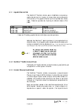
Gigabit Ethernet Port
The StarForm
TM
Swift-G camera uses a GigEVision compliant gi-
gabit ethernet port for transfer of image data and configuration
of the camera. The gigabit ethernet port incorporates two status
LEDs. Table 6.2 provides the meaning for different states of the
LEDs.
LED
State/Colour
Status
GigE LED0
flashing/solid orange
ethernet activity
GigE LED1
flashing green
system is powered
GigE LED1
solid green
link to host established
Table 6.2: Possible gigabit ethernet LED states and interpretation.
Although the StarForm
TM
Swift-G camera is not supplied with an
ethernet cable, it is compatible with standard ethernet cables such
as those available from Allen-Bradley (
https://ab.rockwellautomation.
com/Connection-Devices/RJ45-Network-Media#selection
To comply with with the limits for
a Class A digital device pursuant
to Subpart J of Part 15 of the FCC
Rules, it is required that a shielded
ethernet cable is used.
6.1.2
StarForm
TM
Swift-G Camera Power
The StarForm
TM
Swift-G 3D time-of-flight camera is powered through
a single M12, 12 VDC power connector.
6.1.3
General Purpose Input/Output
The StarForm
TM
Swift-G camera incorporates a single General
Purpose Input Output (GPIO) interface, to allow the user access
to various trigger inputs, strobe outputs, and synchronization ca-
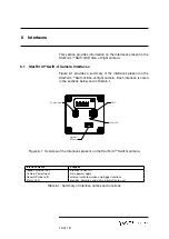
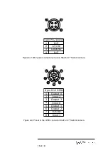
pabilities. The location of the connector is as shown in as shown
in Figure 6.1. Figure 6.3 shows the individual pin assignments for
the connector.
Table 6.3 provides details of the electrical specifications of the
GPIO signals. Inputs are positive logic, i.e. a high voltage is in-
terpreted as a logical 1 within the system. The signal format is
14 of 19


