compatible with 5V CMOS logic levels. Inputs may be driven from
a higher voltage range with the use of a suitable series resistor,
e.g.
1
.
69 k
Ω
for
24 V
levels (max.
28 V
) or
619
Ω
for
12 V
levels
(max.
14 V
). Further details on using GPIO for interface and trig-
gering can be found in the
StarForm
TM
Swift-G User Manual
.
Parameter
MIN
TYP
MAX
Unit
Input voltage range (relative to
IO GND
)
-0.2
5.2
V
Logic low input level
V
I
L
1.3
V
Logic high input level
V
I
H
3.9
V
Input resistance (to
IO GND
)
235
240
Ω
Input forward voltage
V
F
1.0
1.4
1.7
V
Table 6.3: Electrical specifications of GPIO signals.
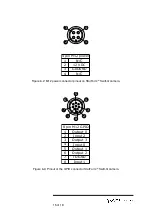
The GPIO signals are electrically isolated. Input sig-
nals must therefore be referred to the
IO GND
pro-
vided on pin 7 of the connector.
Please observe the minimum and maximum voltage
ratings.
Whilst care has been taken to make the
GPIO interface electrically robust, prolonged expo-
sure to signal levels outside these ranges may result
in permanent damage to the system.
6.1.4
Camera Status LEDs
The StarForm
TM
Swift-G camera incorporates a single status LED
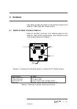
on the rear panel as shown in Figure 6.1. The LED provides in-
formation to the user regarding the internal operation and status
of the camera. Table 6.4 provides the an overview of the meaning
for each state of the LED during startup and operation.
16 of 19

