Rockwell Automation Publication DRIVES-AT005D-EN-P - May 2022
23
Chapter 2 Regenerative Bus Supply Configuration
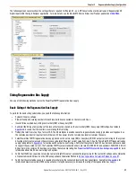
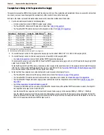
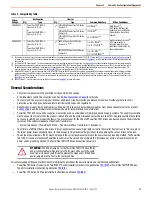
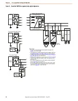
The following screen captures show the settings that are required for 'Shared DC - non-CIP Converter' bus configuration and 'Regeneration OK'
digital input within the Logix Designer application. For more details, see the Kinetix 5700 Servo Drives User Manual, publication
.
Sizing Regenerative Bus Supply
Use one of the following methods to size the PowerFlex 755TM regenerative bus supply.
Basic Sizing of the Regenerative Bus Supply
To perform the basic sizing calculations, you need the following information:
• System AC source voltage.
• Product family and catalog numbers for each inverter/drive connected on the common DC bus.
• Inverter/drive overload duty ratings normal duty (ND) or heavy duty (HD).
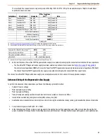
1. Sum/total the DC input amp ratings of the respective inverters, based on the normal duty (ND) / heavy duty (HD) ratings. See tables in
. Assume that the inverters are motoring 100% of rating.
2. Multiply the total from step 1 by a factor of 0.9. The 0.9 multiplier is used because the regenerative bus supply provides a voltage boost so
the common bus inverter input current will be less. DC bus power into the common bus inverter remains the same.
3. Select PowerFlex 755TM regenerative bus supply based on the normal duty (ND) or heavy duty (HD) DC output current rating for the system
AC voltage that meets or exceeds the worst-case calculated DC output current value from step 2. See the PowerFlex 755TM regenerative bus
supply rating tables in
for continuous DC output current ratings. Verify that the system AC and DC bus bars and cables are sized
to support the expected current. The PowerFlex 755TM system standard bus bars are rated for 3000 A DC and optional (-P46) 4700 A DC. All
DC bus bars in the common DC bus lineup must have the same amp rating. See
PowerFlex 755TM System DC Bus Ratings on page 99
for more
information about the DC bus bar ratings and options.
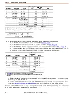
4. Verify that the DC bus capacitance to output amps ratio (µF/A) meets or exceeds the target value for the system AC voltage and combination
of connected inverter/drives. See the DC Bus Capacitance Calculation Method in
DC Bus Capacitance Calculation Method on page 87
5. Verify that the selected bus supply is capable of precharging the connected inverter DC bus capacitance. See tables in
for
internal and maximum external DC bus capacitance. It may be necessary to increase the rating of the regenerative bus supply.


