96
Rockwell Automation Publication DRIVES-AT005D-EN-P - May 2022
Appendix B Power Component Accessories
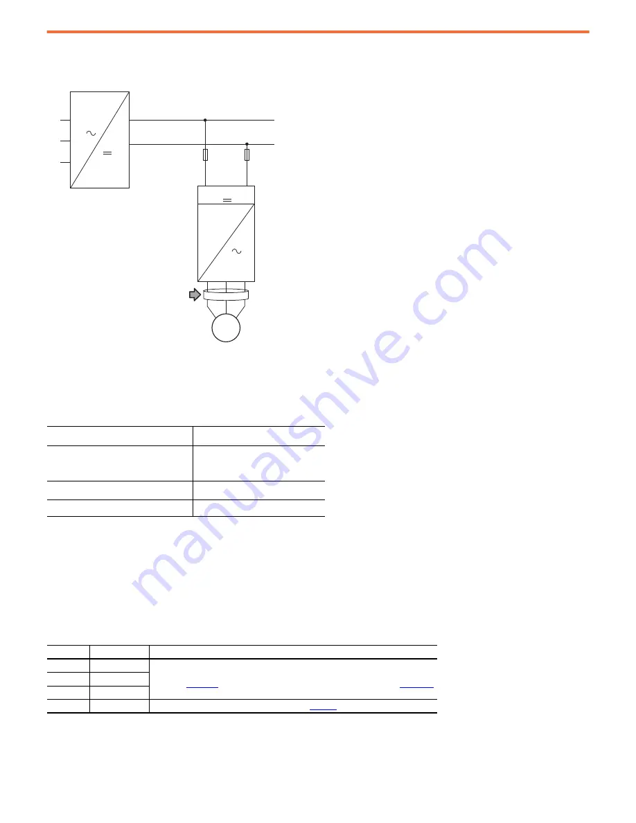
Depending on the device that is used as the DC bus supply, the common mode core can be installed in the locations that are shown in this diagram.
Figure 14 - Common Mode Core Locations
Usage With Regenerative Bus Supply
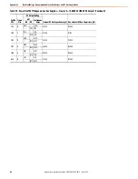
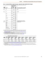
For systems with a PowerFlex® 755TM regenerative bus supply, see the following table. See Figure 18 for locations.
Various core shapes are available to accommodate different arrangements of wire diameters and turn ratios.
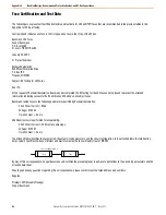
External Common Mode Core Options for Drive
The following external common mode core options are available.
Drive Product Family
Drive Motor Output
(1)
(1) One common mode core at each drive motor output unless an output reactor dv/dt filter is used.
PowerFlex 750-Series
Fr. 1…3:1321-M048
Fr. 4…6:1321-M180
Fr. 7:SK-Y1-CMCORE1
PowerFlex 755TM common bus inverters
Fr. 8…15: Not required
(2)
(2) For PowerFlex 755TM common bus inverters, there are no provisions for AC output common mode
cores; however, an optional reflective wave filter is available. See catalog number position 11-
filtering and CM cap configuration, EMI solutions.
Kinetix® 5700 servo drives
Not required
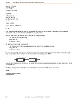
Option
Part No.
Additional Resources
1
1321-M048
For more information, see 1321-Mxxx Common Mode Chokes,
, or Power Conditioning Products Technical Data, publication
2
1321-M180
3
1321-M670
4
SK-Y1-CMCORE1
Contact technical support for more information. See
for design details.
L1
L2
L3
DC+
DC-
DC+
DC-
M
AFE
PowerFlex
AC Drive
Drive Motor
Output

