Parameter Descriptions
11-91
380
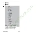
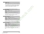
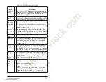
Digital Out1 Sel
Range:
1 = Fault
1
- A fault has occurred and stopped the drive
2 = Alarm
1
- A Type 1 or Type 2 alarm condition exists
3 = Ready - The drive is powered, Enabled and no start
inhibits exist. It is “ready” to run
4 = Run - The drive is outputting voltage and frequency to
the motor (indicates 3–wire control, either direction)
5 = Forward Run - The drive is outputting voltage and
frequency to the motor (indicates 2–wire control in
forward)
6 = Reverse Run - The drive is outputting voltage and
frequency to the motor (indicates 2–wire control in
reverse)
7 = Auto Restart - The drive is currently executing the
Auto Restart or “Run at Power Up” function
8 = Reserved
9 = At Speed - The output frequence equals the
commanded speed
10 = At Freq
2
- The drive output frequency equals or
exceeds the programmed limit
11 = At Current
2
- The drive total output current exceeds
the programmed limit
12 = At Torque
2
- The drive output torque current
component exceeds the programmed limit
13 = At Temp
2
- The drive operating temperature exceeds
the programmed limit
14 = At Bus Volts
2
- The drive bus voltage exceeds the
programmed limit
15 = At PI Error
2
- The drive Process PI Loop error
exceeds the programmed limit
16 = DC Braking - The drive is currently executing either a
“DC Brake” or a “Ramp to Hold” stop command and
the DC braking voltage is still being applied to the
motor.
17 = Curr Limit - The drive is currently limiting output
current
18 = Economize - The drive is currently reducing the
output voltage to the motor to attempt to reduce
energy costs during a lightly loaded situation.
19 = Motor Overld - The drive is currently reducing the
output voltage to the motor to attempt to reduce
energy costs during a lightly loaded situation.
20 = Power Loss - The drive has monitored DC bus
voltage and sensed a loss of input AC power that
caused the DC bus voltage to fall below the fixed
monitoring value (82% of DC bus Memory (13))
21 = Input 1 Link - The digital input value is output on
Dig Out1
22 = Input 2 Link
23 = Input 3 Link
24 = Input 4 Link
25 = Input 5 Link
26 = Input 6 Link
27 = TB in Manual - The terminal block has manual
reference control
Default:
1 = Fault
Access:
1
Path:
Inputs & Output>Digital Outputs
StockCheck.com
Downloaded from StockCheck.com
Summary of Contents for Reliance electric 6SB401 Series
Page 10: ...VIII SP600 AC Drive User Manual S t o c k C h e c k c o m Downloaded from StockCheck com ...
Page 14: ...1 2 SP600 AC Drive User Manual S t o c k C h e c k c o m Downloaded from StockCheck com ...
Page 48: ...Mounting the Drive 3 12 S t o c k C h e c k c o m Downloaded from StockCheck com ...
Page 86: ...Installing Control Wiring 7 14 S t o c k C h e c k c o m Downloaded from StockCheck com ...
Page 102: ...10 8 SP600 AC Drive User Manual S t o c k C h e c k c o m Downloaded from StockCheck com ...
Page 232: ...Technical Specifications A 8 S t o c k C h e c k c o m Downloaded from StockCheck com ...
Page 248: ...B 16 SP600 AC Drive User Manual S t o c k C h e c k c o m Downloaded from StockCheck com ...
Page 256: ...C 8 SP600 AC Drive User Manual S t o c k C h e c k c o m Downloaded from StockCheck com ...
Page 258: ...D 2 SP600 AC Drive User Manual S t o c k C h e c k c o m Downloaded from StockCheck com ...
Page 260: ...E 2 SP600 AC Drive User Manual S t o c k C h e c k c o m Downloaded from StockCheck com ...
Page 266: ...F 6 SP600 AC Drive User Manual S t o c k C h e c k c o m Downloaded from StockCheck com ...
Page 273: ...S t o c k C h e c k c o m Downloaded from StockCheck com ...

