Troubleshooting the Drive
12-5
12.4
About Alarms
Alarms indicate conditions that may affect drive operation or
application performance.
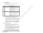
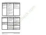
There are two alarm types, as described in table 12.3.
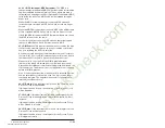
The drive indicates alarm conditions in the following ways:
• Ready LED on the drive cover (see table 12.2).
• Alarm name and bell graphic on the LCD OIM (see Appendix B).
The alarm is displayed as long as the condition exists. The drive
automatically clears the alarm when the condition causing it is
removed.
• Alarm status parameters. Two 16-bit parameters, Drive Alarm 1
(211) and Drive Alarm 2 (212), indicate the status of type 1 and
type 2 alarms, respectively. Refer to chapter 11 for the parameter
descriptions.
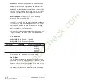
12.4.1 About the Alarm Queue
The drive automatically retains a history of alarms that have
occurred in the alarm queue. The alarm queue is accessed using
the OIM or PC software.
The alarm queue holds the eight most recent alarms. The last alarm
to occur is indicated in queue entry #1. As new alarms are logged
into the queue, existing alarm entries are shifted (for example, entry
#1 will move to entry #2). Once the queue is full, older alarms are
discarded from the queue as new alarms occur.
All entries in the alarm queue are retained if power is lost. Alarms
are automatically cleared when the alarm condition goes away.
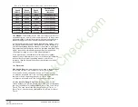
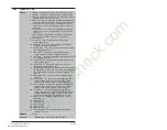
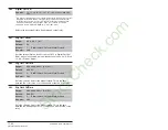
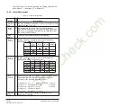
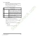
Table 12.3 – Types of Alarms
Type
Alarm Description
User-Configurable
These alarms alert the operator of conditions
that, if left untreated, may lead to a fault
condition. The drive continues to operate
during the alarm condition.
The alarms are enabled or disabled using
Alarm Config 1 (259).
The status of these alarms is shown in Drive
Alarm 1 (211).
Non-Configurable
These alarms alert the operator of conditions
caused by improper programming and prevent
the drive from starting until the problem is
resolved.
These alarms are always enabled.
The status of these alarms is shown in Drive
Alarm 2 (212).
StockCheck.com
Downloaded from StockCheck.com
Summary of Contents for Reliance electric 6SB401 Series
Page 10: ...VIII SP600 AC Drive User Manual S t o c k C h e c k c o m Downloaded from StockCheck com ...
Page 14: ...1 2 SP600 AC Drive User Manual S t o c k C h e c k c o m Downloaded from StockCheck com ...
Page 48: ...Mounting the Drive 3 12 S t o c k C h e c k c o m Downloaded from StockCheck com ...
Page 86: ...Installing Control Wiring 7 14 S t o c k C h e c k c o m Downloaded from StockCheck com ...
Page 102: ...10 8 SP600 AC Drive User Manual S t o c k C h e c k c o m Downloaded from StockCheck com ...
Page 232: ...Technical Specifications A 8 S t o c k C h e c k c o m Downloaded from StockCheck com ...
Page 248: ...B 16 SP600 AC Drive User Manual S t o c k C h e c k c o m Downloaded from StockCheck com ...
Page 256: ...C 8 SP600 AC Drive User Manual S t o c k C h e c k c o m Downloaded from StockCheck com ...
Page 258: ...D 2 SP600 AC Drive User Manual S t o c k C h e c k c o m Downloaded from StockCheck com ...
Page 260: ...E 2 SP600 AC Drive User Manual S t o c k C h e c k c o m Downloaded from StockCheck com ...
Page 266: ...F 6 SP600 AC Drive User Manual S t o c k C h e c k c o m Downloaded from StockCheck com ...
Page 273: ...S t o c k C h e c k c o m Downloaded from StockCheck com ...

