12-18
SP600 AC Drive User Manual
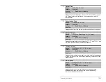
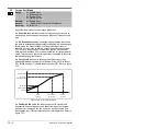
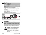
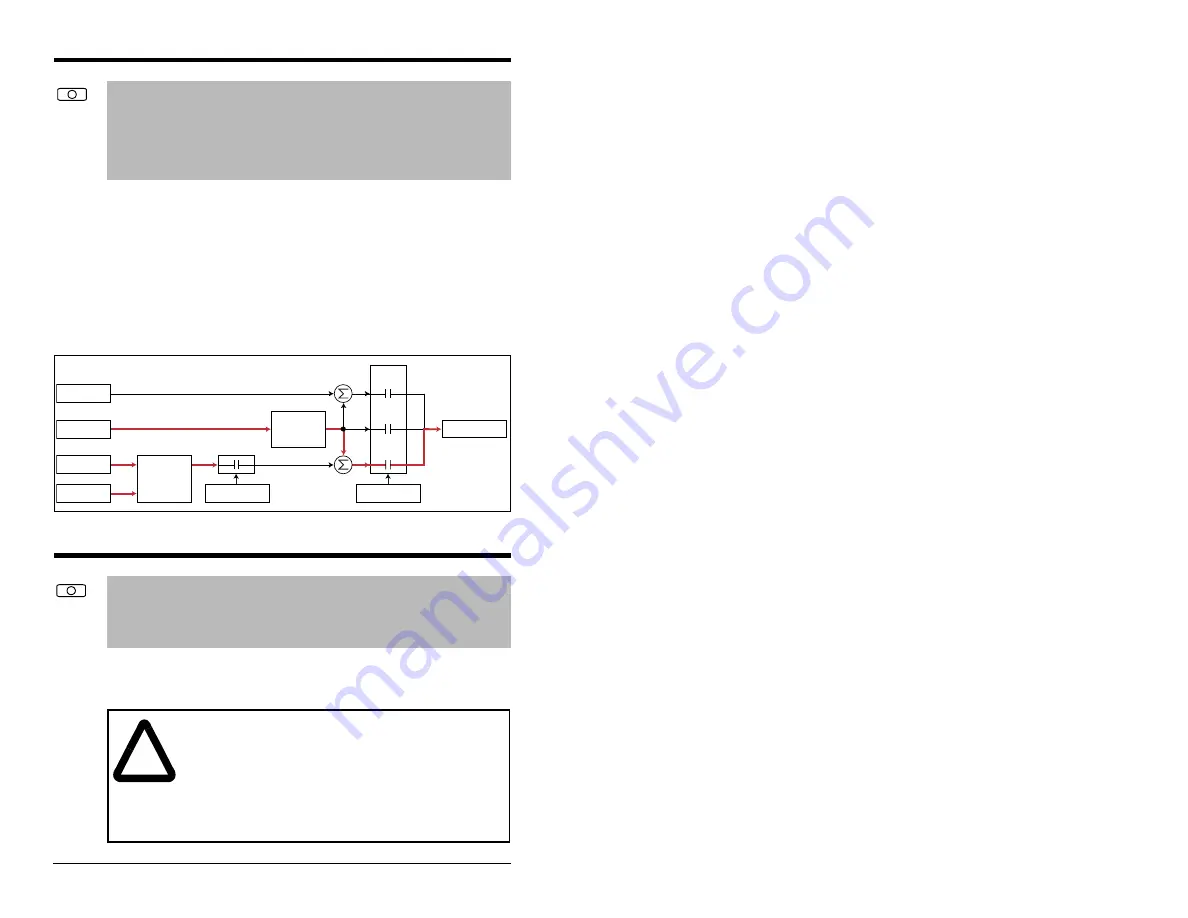
Sets the method of speed regulation. See figure 12.6.
0 = Open Loop provides no speed compensation due to load
variations. This is strict volts per hertz output as a function of the
speed reference.
1 = Slip Comp provides for frequency output adjustment as a
function of load. The amount of compensation is defined by the
value of Slip RPM @ FLA.
2 = Process PI allows for the output motor speed (frequency) to be
adjusted based on the outer control loop regulator.
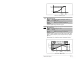
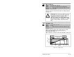
Sets the low limit for the speed reference after scaling is applied.
See figure 12.7.
80
Speed Mode
Range:
0 = Open Loop
1 = Slip Comp
2 = Process PI
Default:
0 = Open Loop
Access:
2
Path: Speed Command>Spd Mode & Limits
See also:
124 -138
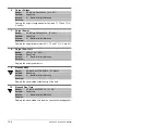
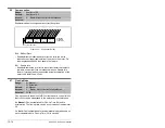
Figure 12.6 – Speed Control Method
+
Spd Cmd
Process PI
Controller
Linear Ramp
& S-Curve
+
+
+
PI Disabled
Speed Control
Spd Ref
PI Ref
PI Fbk
Slip Adder
Open
Loop
Slip
Comp
Process
PI
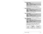
81
Minimum Speed
Range:
0.0 to Maximum Speed [0.1 Hz]
Default:
0.0 Hz
Access:
0
Path: Speed Command>Spd Mode & Limits
See also:
83, 92, 95
!
ATTENTION: The drive can operate at and maintain
zero speed. The user is responsible for assuring safe
conditions for operating personnel by providing
suitable guards, audible or visual alarms, or other
devices to indicate that the drive is operating or may
operate at or near zero speed. Failure to observe
this precaution could result in severe bodily injury or
loss of life.
Summary of Contents for Reliance electric 6SP201-015
Page 14: ...1 2 SP600 AC Drive User Manual ...
Page 54: ...Mounting the Drive 3 16 ...
Page 82: ...6 12 SP600 AC Drive User Manual ...
Page 96: ...7 14 SP600 AC Drive User Manual ...
Page 232: ...Parameter Descriptions 12 102 ...
Page 280: ...B 8 SP600 AC Drive User Manual ...
Page 282: ...C 2 SP600 AC Drive User Manual ...
Page 284: ...D 2 SP600 AC Drive User Manual ...
Page 298: ......
Page 299: ......

