Parameter Descriptions
12-31
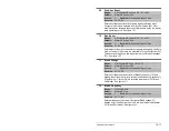
Bit 4 - Zero Clamp
• Enables/disables option to limit operation so that the output
frequency of the PI regulator always has the same sign as
the master speed reference. This limits the possible drive
action to one direction only. Output from the drive will be from
zero to maximum frequency forward or zero to maximum
frequency reverse.
Bit 5 - Feedback Sqrt (Square Root Feedback)
• Enables/disables the option of using the square root of the
feedback signal as the PI feedback.
Controls the PI regulator. You can control the bits from a Datalink
network parameter or an assigned digital input.
PI control allows the drive to take a reference signal (setpoint) and
an actual signal (feedback) from an external transducer such as
position, flow, or pressure, so that the motor speed can be adjusted
to maintain control over the external variable.
Proportional control (P) adjusts the output based on the size of the
error (larger error = proportionally larger correction).
Integral control (I) adjusts the output based on the duration of the
error. The integral control by itself is a ramp output correction. This
type of control gives a smoothing effect to the output and will
continue to integrate until zero error is achieved.
By itself, integral control is slower than many applications require,
and, therefore, is combined with proportional control (PI).
There are two ways the PI regulator can be configured to operate
(see parameter 124):
• Process trim, which takes the output of the PI regulator and sums
it with a master speed reference to control the process.
• Process control, which takes the output of the PI regulator as the
speed command. No master speed reference exists, and the PI
output directly controls the drive output.
Note that Speed Mode (80) must be set to Process PI (2).
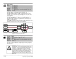
125
PI Control
Range:
See figure 12.14
Default:
See figure 12.14
Access:
2
Path: Speed Command>Process PI
See also:
124-138
Summary of Contents for Reliance electric 6SP201-015
Page 14: ...1 2 SP600 AC Drive User Manual ...
Page 54: ...Mounting the Drive 3 16 ...
Page 82: ...6 12 SP600 AC Drive User Manual ...
Page 96: ...7 14 SP600 AC Drive User Manual ...
Page 232: ...Parameter Descriptions 12 102 ...
Page 280: ...B 8 SP600 AC Drive User Manual ...
Page 282: ...C 2 SP600 AC Drive User Manual ...
Page 284: ...D 2 SP600 AC Drive User Manual ...
Page 298: ......
Page 299: ......


