12-42
SP600 AC Drive User Manual
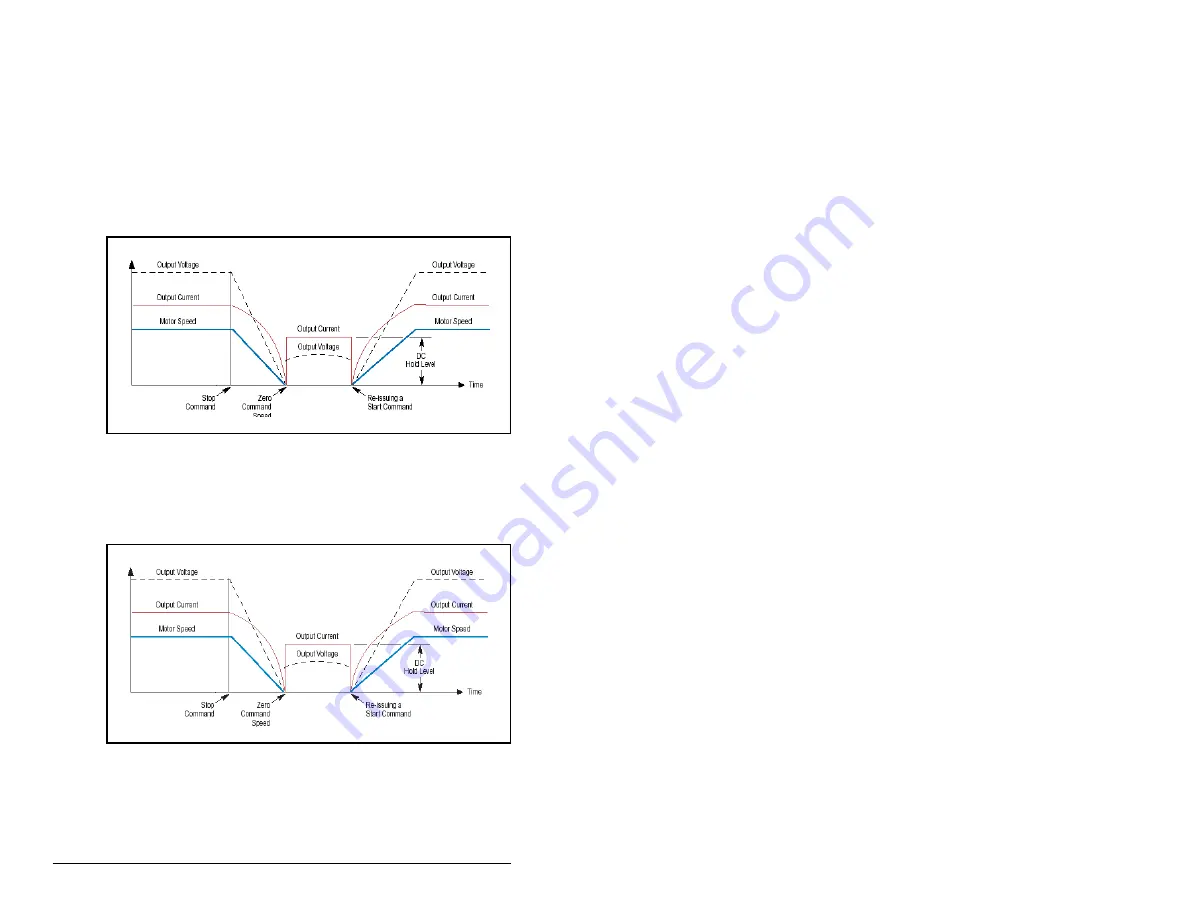
2 = Ramp to Hold: When Stop Mode A (155) is set to Ramp to
Hold, the drive ramps the frequency to zero based on the
deceleration time programmed into Decel Time 1 (142) or Decel
Time 2 (143). Once the drive reaches zero hertz, a DC injection
holding current is applied to the motor based on the values set in
DC Brake Level (158) and DC Brake Lvl Sel (157). The DC hold is
removed only by removing the Enable input or by a valid start input.
Motor speed during and after the application of DC depends on the
combination of these two parameter settings and the mechanical
system. The drive output voltage will be zero when the hold time is
finished.
3 = DC Brake - When Stop Mode A (155) is set to DC Brake, the
drive acknowledges the Stop command by immediately stopping the
output and then applying a programmable DC voltage (DC Brake
Level (158)) to one phase of the motor.
You can also select the amount of time the braking will be applied
and the magnitude of the current used for braking with DC Brake
Time (159) and DC Brake Level (158). This method of braking will
generate up to 40% of rated motor torque for braking and is typically
used for low inertia loads.
Figure 12.21 – Ramp to Hold (Stop Mode A = 2)
Figure 12.22 – DC Brake (Stop Mode A = 3)
Summary of Contents for Reliance electric 6SP201-015
Page 14: ...1 2 SP600 AC Drive User Manual ...
Page 54: ...Mounting the Drive 3 16 ...
Page 82: ...6 12 SP600 AC Drive User Manual ...
Page 96: ...7 14 SP600 AC Drive User Manual ...
Page 232: ...Parameter Descriptions 12 102 ...
Page 280: ...B 8 SP600 AC Drive User Manual ...
Page 282: ...C 2 SP600 AC Drive User Manual ...
Page 284: ...D 2 SP600 AC Drive User Manual ...
Page 298: ......
Page 299: ......


