background image

PREFACE 

Trusted High Integrity Power Supply System 


ii 

Issue 11 

Rockwell Automation Publication PD_T8200 

DOCUMENTATION FEEDBACK 

Your comments help us to write better user documentation. If you discover an error, or have a 

suggestion on how to make this publication better, send your comment to our technical support 

group at 

http://rockwellautomation.custhelp.com


Summary of Contents for Trusted T8220

Page 1: ...nverts redundant main line voltages of either 110 Vac 240 Vac or 24 Vdc to 15 Vdc or 24 Vdc output power for system and field power requirements Features Redundant power inputs 250 W Hot replaceable Current sharing Power factor correction Front panel indicators for input output voltage status and output current level on each module External status signals TϋV Certified IEC 61508 SIL 3 ...

Page 2: ...Trusted PD_T8200 Rockwell Automation Publication PD_T8200 Issue 11 Page intentionally left blank ...

Page 3: ...based on information available at the time of its publication The document contents are subject to change from time to time The latest versions of the manuals are available at the Rockwell Automation Literature Library under Product Information information Critical Process Control Safety Systems TRUSTED RELEASE This technical manual applies to Trusted Release 3 6 1 LATEST PRODUCT INFORMATION For t...

Page 4: ...tion Publication PD_T8200 DOCUMENTATION FEEDBACK Your comments help us to write better user documentation If you discover an error or have a suggestion on how to make this publication better send your comment to our technical support group at http rockwellautomation custhelp com ...

Page 5: ...an cause an explosion in a hazardous environment which can cause injury or death property damage or economic loss ATTENTION Identifies information about practices or circumstances that can cause injury or death CAUTION Identifies information about practices or circumstances that can cause property damage or economic loss BURN HAZARD Identifies where a surface can reach dangerous temperatures If a ...

Page 6: ... ou équivalente MAINTENANCE Maintenance must be carried out only by qualified personnel Failure to follow these instructions may result in personal injury CAUTION RADIO FREQUENCY INTERFERENCE Most electronic equipment is influenced by Radio Frequency Interference Caution should be exercised with regard to the use of portable communications equipment around such equipment Signs should be posted in ...

Page 7: ... Publication PD_T8200 Issue 11 v ISSUE RECORD Issue Date Comments 8 Sep 05 Format 9 Mar 06 Removed hidden characters 10 Sep 15 Rebranded and reformatted 11 Apr 16 Standardisation of Operating Temperature and Relative Humidity Range Statements in the Specification section ...

Page 8: ...PREFACE Trusted High Integrity Power Supply System vi Issue 11 Rockwell Automation Publication PD_T8200 Page intentionally left blank ...

Page 9: ...r 7 1 4 2 Output Power Display 7 1 4 3 Output Power Indicator 7 2 Installation 9 2 1 Chassis Mounting 9 2 2 Backplane Versions and Module Keying 10 2 2 1 Input Power Terminals TB1 TB2 8 Screw Terminals 10 2 2 2 Output Power Terminals TB3 TB4 6 Screw Terminals 11 2 2 3 Status Connectors J14 J15 11 2 2 4 Monitor Connector J13 12 3 Configuration 13 3 1 Current Sharing 13 3 2 REGENT Power Supply Load ...

Page 10: ...Table of Contents Trusted High Integrity Power Supply System 2 Issue 11 Rockwell Automation Publication PD_T8200 Page intentionally left blank ...

Page 11: ...ules providing field power in a N 1 configuration Alternatively the Chassis may be set up to provide separate dual 24 Vdc supplies for both a Trusted System and associated field devices Figure 1 Power Supply Assembly 1 1 Power Supply Chassis The Power Supply Chassis houses a maximum of six Power Supply Modules It may be mounted in a 19 inch rack or flush mounted on a panel Table 1 identifies the a...

Page 12: ...4 Vdc 24 Vdc Table 2 Module Types The dual inputs on the ac Modules are galvanically isolated from each other The inputs on the dc Modules are diode isolated and share a common return 1 3 Input Power Regulation A block diagram of a typical dual ac input I O Power Supply Module is shown in Figure 2 A block diagram of a typical dual dc input I O Power Supply Module is shown in Figure 3 Figure 2 Bloc...

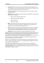
Page 13: ...put modules only Indicates the dc bulk voltage power factor correction PFC output is outside the specified range There is a separate signal for each input High temperature warning alarm Both an active high and active low status output are provided Indicates when the module temperature exceeds 75 C The temperature is sensed near the air inlet bottom of the module High temperature shutdown Internal ...

Page 14: ...This signal provides the capability to test the input circuitry of a module by turning off each input independently while monitoring the module fail signal Remote off Active low input that turns off the output power of a module Note Bulk Power Fail PFC Off and Remote Off are accessed through the Monitor Module Connector on the chassis backplane The Monitor Module Connector allows for a future deve...

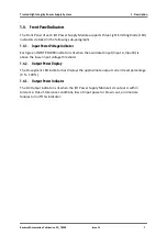
Page 15: ...Voltage Indicator Each green INPUT POWER indicator is lit when the associated input Input A Input B is above the lower input voltage threshold 1 4 2 Output Power Display The 10 segment LED indicator bar displays the approximate output current level percentage 0 100 1 4 3 Output Power Indicator The DC Output indicator is lit when the I O Power Supply Module s dc output is within tolerance Out of to...

Page 16: ...1 Description Trusted High Integrity Power Supply System 8 Issue 11 Rockwell Automation Publication PD_T8200 Page intentionally left blank ...

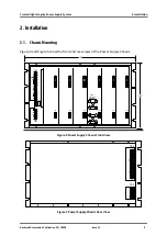
Page 17: ...sue 11 9 2 Installation 2 1 Chassis Mounting Figure 4 and Figure 5 show the front and rear views of the Power Supply Chassis TB3 J13 J15 TB1 J14 19 10 5 J1 J2 J3 J4 J6 J5 J7 J8 J12 J11 J9 J10 Input Crossover Patch Figure 4 Power Supply Chassis Front View Figure 5 Power Supply Chassis Rear View TB4 TB2 ...

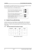
Page 18: ...gured to swap source 1 and source 2 for modules slots 4 through 6 Source 1 and source 2 are connected to input A and input B respectively for slots 1 3 Source 1 and source 2 are connected to input B and input A respectively for slots 4 6 2 2 Backplane Versions and Module Keying Connector placement on ac Input Modules and backplanes differ from dc modules and backplanes This prohibits insertion of ...

Page 19: ...202 12 6 DC Output 11 5 10 4 9 3 8 2 7 1 6 5 4 1 6 DC Return terminals 1 6 are connected together on Backplane 3 2 1 Table 4 Output Power Terminals 2 2 3 Status Connectors J14 J15 Type 10 pin shrouded header double row 0 100 x 0 100 Centres Manufacturer AMP Manufacturer Part No 102618 3 Mating Connector AMP 87631 5 Pin Out Pin J14 J15 Slot Signal Slot Signal 1 2 All Input A Fail 3 All Input B Fail...

Page 20: ...t Signal 4 All Hi Temperature 5 1 Reset 4 Reset 6 1 Power Fail 6 Reset 7 2 Reset 4 Power Fail 8 3 Power Fail 6 Power Fail 9 2 Power Fail 5 Power Fail 10 3 Reset 5 Reset Table 5 Status Connectors 2 2 4 Monitor Connector J13 Type 72 pin Edge Connector 0 125 in centreline Manufacture AMP Manufacturer Part No 1 530844 9 Pin out Not Configured ...

Page 21: ...ng load units Number of I O Units Chassis 1 2 3 4 Load Unit Capacity 82 78 74 70 Table 6 Available Load Units for a set of three power supplies Calculating the number of load units in the system helps determine the number of I O Power Supplies required by the system For economic power distribution and to avoid overloading individual Power Supply Units calculate power supply loading when configurin...

Page 22: ...nfiguration Trusted High Integrity Power Supply System 14 Issue 11 Rockwell Automation Publication PD_T8200 I O Transceivers and I O Modules require power fail and reset status signals for proper operation ...

Page 23: ...nance No periodic maintenance or calibration is required for I O Power Supply Modules There are no user replaceable parts A failed I O Power Supply Module can be hot replaced without disrupting system operations Main power wiring and I O power cables connected to the Chassis are not disturbed during Module replacement ...

Page 24: ...4 Maintenance Trusted High Integrity Power Supply System 16 Issue 11 Rockwell Automation Publication PD_T8200 Page intentionally left blank ...

Page 25: ...c T8220 T8223 T8224 T8225 20 4 0A peak Cold 35 65 A peak Hot Power Factor 0 95 min Efficiency 70 Use with Chassis T8220 T8223 T8224 T8225 T8200 T8222 T8226 T8202 Fusing Internal to module T8220 T8223 T8224 T8225 6 A 250 V 3AG Slow Blow T8222 T8226 20 A 250 V 3AB Slow Blow Output Voltage T8220 T8222 T8224 15 Vdc T8223 T8225 T8226 24 Vdc Output Power 250 W per module Power Hold up Time T8220 T8223 T...

Page 26: ...F to 158 F Relative Humidity range operating storage transport 10 95 non condensing Environmental Specifications Refer to document 552517 Module Dimensions Height 266 mm 10 47 in Width 61 mm 2 38 in Depth 318 mm 2 5 in Chassis Dimensions Height 266 mm 10 47 in Width 483 mm 19 in Depth 343 mm 13 5 in Module Weight 3 25 kg 7 2 lb Chassis Weight 7 kg 15 4 lb ...

Reviews: