16
E10037-180424
PROBEX
WARNING: Stop pumping when the deflation circuit pressure gauge reaches
7000 kPa (1000 psi.) to avoid damaging the PROBEX
STEP 8. Place the pump
’s small handle on position 1 and activate the pump. If air is present
in the probe, bubbles will be seen out of the tubing. Continue until air bubbles are
no longer present and only water is coming out of the tubing. Repeat sucking in
and expulsing water out of the probe until no air bubbles are expelled, which will
mean that saturation is complete. Then fully retract the piston.
STEP 9. Remove the tubing and screw the saturation plug back onto the steel core taking
care to put 3-4 layers of Teflon tape on the plug's threads. Screw the stainless
steel, conical end cap back onto the probe.
2.4
CALIBRATION OF THE PROBEX
Two types of calibration must be run.
Note that
two short hydraulic lines
can be used for speeding up calibration processes.
2.4.1 PRESSURE LOSS CALIBRATION
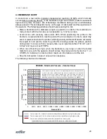
The pressure calibration allows determining the PROBEX membrane stiffness (inertia),
which must be deducted from pressure readings obtained during a test. The membrane
stiffness is equivalent to the pressure necessary to dilate the unconfined probe. This
calibration must be done a single time when using a new membrane. The procedure
consists of:
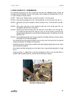
STEP 1. Once the whole system is saturated, place the probe horizontally at ground level
next to the pump. Inflate and deflate the probe two times in order to knead the
membrane. Then bring the piston back to 0 cm
3
.
STEP 2. Inflate the probe the in increments of 50 cm
3
up to 650 cm
3
. Following each volume
increment, the corresponding pressure is recorded after one minute. Draw the
pressure correction curve.
The softer the rock, the greater the influence of the pressure calibration is.
2.4.2 VOLUME LOSS CALIBRATION
The volume calibration allows determining the correction corresponding to the deformation
of the equipment when pressurized. This deformation comes essentially from membrane
squeezing and from the compression of the small quantity of air in the water. It must be
deducted from volume readings obtained during a test.
The calibration consists of inflating the probe up to 30 MPa in the calibration tube in pressure
increments typically of 3 MPa. This calibration allows to: check for leaks, knead the
membrane, and determine
‘c’
(probe deformation)
The volume correction factor ‘
c
’ is given by the following equation
c = a
– b.
Where
‘a’
is the PROBEX volumetric expansion obtained from the Volume Calibration, and
‘b’
corresponds to the (small) theoretical expansion of the calibration tube when
pressurized.


