background image


GuardCom Installation Manual 


guardcom_installation_manual_v1.0.docm 


Publicly available


 p. 21 of 31 

7. 

Fully mounted: 


5


GuardCom connections and communication 


As described in section 2 the GuardCom System takes care of the communication from robot to 
conveyor station.  

The line of communication and supply is illustrated here: 


Figure 11. Schematic overview of connections and communication through the GuardCom System from robot to conveyor station. 
From the left: 
The MiR robot supplies and communicates with the ROEQ top module. 
The GuardCom Connect is embedded into the ROEQ top module (section 4) and 
gets its signals and supply from here. 
The GuardCom Connect communicates with the GuardCom via light signals both ways. 
The GuardCom communicates with the conveyor station via a nine pin communication cable and is powered through a 24 V supply 
cable. 


Conveyor


station


(any brand)


ROEQ 

top module


GuardCom 

Connect 


24V


Communication


GuardCom


Communication


Communication


Supply


MiR


robot 


Communication


Supply


Summary of Contents for GuardCom

Page 1: ...GuardCom Installation Manual including GuardCom Connect 2020 12 23...

Page 2: ...nts In addition the contents of the document are subject to change without prior notice Every precaution has been taken in the preparation of this document Nevertheless ROEQ assumes no responsibility...

Page 3: ...2 1 Option B continued Installation of GuardCom 14 3 2 2 Option B continued Installation of custom made VL Marker 17 4 Mounting of GuardCom Connect 19 4 1 Mounting of GuardCom Connect on TR500 1000 19...

Page 4: ...rdCom System 1 1 Limitations This document does not resemble a complete User Manual It serves to describe the physical installation and to explain the product functionality for usage in the planning a...

Page 5: ...ted between the conveyor station and the pick up delivery point for the robot The receiving station can serve as a buffer where goods can be parked until it is picked up by the robot or until a receiv...

Page 6: ...rimary physical stop to keep heavy goods from rolling off the conveyor station 2 Communication The GuardCom System facilitates wireless communication between robot and conveyor station eliminating usa...

Page 7: ...The GuardCom System works with any kind of conveyor stations and the entire product range of ROEQ top rollers All ROEQ top rollers come with ROEQ s setup software to facilitate easy setup of the top r...

Page 8: ...n using ROEQ DS Standalone is 1 Installation of DS Standalone with VL Marker section 3 1 1 2 Installation of the GuardCom section 3 1 2 It is crucial for the functionality of GuardCom that it is align...

Page 9: ...ust be positioned parallel to the rolls on the conveyor station This is crucial for the GuardCom functionality and it is important to make the rolls on the conveyor station and on the ROEQ top roller...

Page 10: ...ial ROEQ product Once the DS Standalone is mounted the GuardCom should be attached to the conveyor station following these guidelines Step Instruction and illustration 4 The GuardCom must be placed in...

Page 11: ...ndalone It must be ensured that the chassis blue part has appropriate strength and that it is properly attached to the conveyor station 7 Utilize the two threaded holes on the back of the GuardCom to...

Page 12: ...The depth must be between 14 and 17 mm 0 55 0 75 If the bolts are too short the GuardCom might not be securely attached to the frame chassis 9 Mount the ROEQ Reflector on the GuardCom Correct position...

Page 13: ...e VL Marker must be positioned as advised in section 3 2 2 3 The VL Marker must follow the geometrical specification set out by MiR It is strongly recommended to comply with all three points as they a...

Page 14: ...cted conveyor station is not a commercial ROEQ product Follow these guidelines to install the GuardCom with a custom made VL Marker Step Instruction and illustration 1 The GuardCom must be placed in t...

Page 15: ...be centered in relation to the rolls on the conveyor station The offset from center should be less than 1 mm 0 04 3 Utilize the two threaded holes on the back of the GuardCom to fasten it to the frame...

Page 16: ...The depth must be between 14 and 17 mm 0 55 0 75 If the bolts are too short the GuardCom might not be securely attached to the frame chassis 5 Mount the ROEQ Reflector on the GuardCom Correct position...

Page 17: ...work as intended The following instructions presuppose that the custom made VL Marker complies with the specifications set out by MiR Step Instruction and illustration 6 The VL Marker must be position...

Page 18: ...83 1 mm 3 27 0 04 8 The VL Marker must be placed in the correct height h as prescribed by MiR 9 The front of the VL Marker must be parallel to the rolls on the conveyor station This is crucial for the...

Page 19: ...in this document 4 1 Mounting of GuardCom Connect on TR500 1000 The GuardCom Connect is installed on to the TR500 1000 as part of the installation of TR500 1000 on the MiR robot Refer to the installa...

Page 20: ...t to gain access 5 Make sure the GuardCom Connect cable runs on the inside of the flanges Connect the GuardCom Connect cable to its counterpart at the control box 6 Mount the screws for the side cover...

Page 21: ...ardCom System from robot to conveyor station From the left The MiR robot supplies and communicates with the ROEQ top module The GuardCom Connect is embedded into the ROEQ top module section 4 and gets...

Page 22: ...sed by the GuardCom pin 5 in order to maintain the electrical separation The isolated ground signal exposed by the GuardCom pin 6 may be employed by the end user to introduce a common ground between t...

Page 23: ...ass the signal guardcom_is_ready by turning on the light emitter situated on the GuardCom This indicate that the GuardCom is ready to transfer receive cargo The two signals act as handshake between th...

Page 24: ...A 6 gnd_isolated Output This isolated ground signal exposed by the GuardCom may be employed by the end user to introduce a common ground between the GuardCom electric circuit and the external system s...

Page 25: ...conveyor station robot_is_ready guardcom_is_ready robot_is_ready guard_is_open guard_is_closed guard_is_blocked Allowed to roll Robot in place and ready to transfer package robot_is_ready guardcom_is...

Page 26: ...In this setting the input signal confirm_ready must be set high for the guardcom_is_ready light to be turned on This can be used to communicate to the robot that the emergency stop on the conveyor sta...

Page 27: ...Jumper 2 E15 E16 Jumper 3 E22 E23 default robot_is_ready on ok_to_open on robot_is_ready off ok_to_close on Guard fully open robot_is_ready on Table 5 6 3 Three control options jumper setting The thr...

Page 28: ...l guard_is_blocked is sent to the conveyor station The guard_is_blocked signal must bring the rolls on the conveyor station to a stop immediately The Blocked Guard function will only set in if the obs...

Page 29: ...issue a protective stop on the robot Figure 16 Protective stop on the robot is issued in the event that the guardcom_is_ready signal is turned off whilst a package is being transferred NB Note that th...

Page 30: ...losing by package robot_is_ready guardcom_is_ready robot_is_ready guard_is_open guard_is_closed guard_is_blocked Braked Table 6 Functionality when emergency stop on robot is triggered Rolls on conveyo...

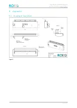
Page 31: ...GuardCom Installation Manual guardcom_installation_manual_v1 0 docm Publicly available p 31 of 31 9 Appendix 9 1 Drawing of GuardCom Figure 17...

Reviews: