


ES
165
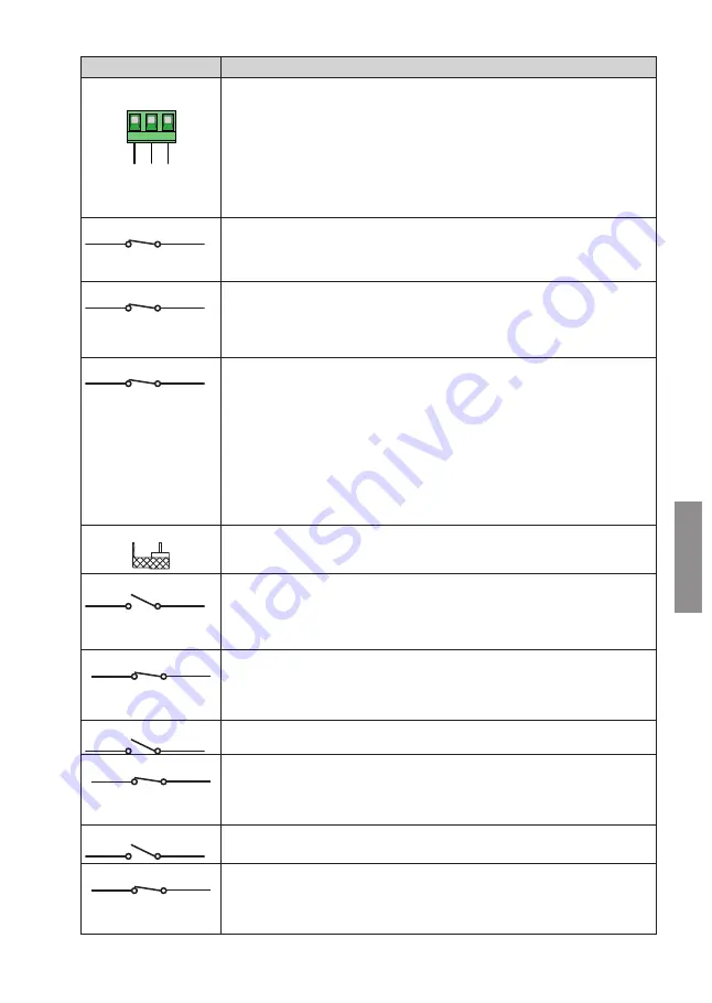
CONTACTO
DESCRIPCIÓN
18(COM)-19(LNA)-20(LNB)
CO
M
LN
A
LNB
18 19 20
Funcionamiento.
La comunicación serial permite efectuar la sincronización entre las barreras.
Si interviene un obstáculo se invierte inmediatamente el movimiento del asta que lo ha detectado, la otra
invertirá el movimiento con un retraso fijo.
Si la barrera MASTER está completamente abierta o completamente cerrada y la barrera SLAVE se
encuentra en una posición intermedia, la barrera MASTER envía una orden de realineación de la barrera
SLAVE con un predestello fijo de 5 s.
Si por el contrario la barrera MASTER se encuentra en la posición intermedia, después de los 5 s de pre-
destello se realinea con la barrera SLAVE.
La alineación no es viable si está activada la función de hombre presente
$
.
21(ST) 22(COM)
Entrada de comando de STOP (N.C.).
La apertura del contacto de seguridad provoca la parada del movimiento.
NOTA:
el contacto llega conectado con puente de fábrica por ROGER TECHNOLOGY. En instalaciones con
dos barreras contrapuestas, si la orden de STOP se da a la barrera MASTER se pararán ambas barreras.
Si se da la orden de STOP a la barrera SLAVE, solo la barrera SLAVE se detendrá.
23(COS) 22(COM)
Entrada (N.C. o 8.2 kOhm) para conexión del borde sensible
COS
.
La actuación del borde sensible durante el cierre provoca la inversión de la maniobra (reapertura).
Si el borde sensible no está instalado, conecte con puente los bornes
23(COS)-22(COM)
o
seleccione
el parámetro
.
En instalaciones con dos barreras contrapuestas, el borde sensible (si lo lleva) ha de conectarse y
configurarse tanto en la barrera MASTER como en la barrera SLAVE.
24(FT) 13(COM)
Entrada (N.C.) para conexión de la fotocélula
FT
(fig. 4-5).
Le fotocélulas llegan configuradas de fábrica de la manera siguiente::
–
. La fotocélula actúa solo durante la fase de cierre. Se ignorará en la fase de apertura.
–
. Durante el cierre la actuación de la fotocélula provoca la inversión del movimiento.
–
. La barrera se abre al recibir un comando de apertura aunque la luz de la fotocélula FT
quede interrumpida.
Si las fotocélulas no están instaladas, conecte con puente los bornes
24(FT)
-
13(COM)
o seleccione
los parámetros
y
.
¡ATENCIÓN!
Se aconseja instalar fotocélulas de la serie
G90/F4ES
o
T90/F4S.
En instalaciones con dos barreras contrapuestas las fotocélulas han de conectarse y configurarse solo
en la barrera MASTER.
En instalaciones con modo de aparcamiento, la entrada
FT
puede utilizarse como orden de cierre dada
por una espira magnética (N.C.) (véase capítulo 14).
27 26(ANT)
Conexión enchufable de la antena para receptor de radio.
Si se utiliza la antena exterior, utilice cable RG58, longitud máxima aconsejada: 10 m.
NOTA:
no efectúe empalmes en el cable.
29(PED) 28(COM)
Entrada del comando de apertura parcial (N.A.).
El cierre del contacto causa siempre la apertura total de la barrera.
En caso de dos barreras contrapuestas, la orden PED abre la barrera MASTER solo cuando las dos
barreras están completamente cerradas
En instalaciones con modo de aparcamiento "Direccional" (parámetro
o
) la entrada PED
puede utilizarse como orden de apertura dada por la espira magnética (véase capítulo 14).
29(PED) 28(COM)
Entrada de mando (N.C.) disponible para la conexión del sensor del sistema de conexión del asta de las
barreras con desenganche
ACS/BA/60
(fig. 8)
Cuando interviene el sistema de seguridad de conexión de la hoja con desenganche ACS/BA/60, el
contacto pasa de N.C. a N.O.
Habilitar la entrada con el parámetro
.
30(PP) 28(COM)
Entrada del comando paso a paso (N.A.).
El funcionamiento del comando está regulado por el parámetro
$
.
30(PED) 28(COM)
Entrada de mando (N.C.) disponible para la conexión del sensor del sistema de conexión del asta de las
barreras con desenganche
ACS/BA/60
(fig. 8)
Cuando interviene el sistema de seguridad de conexión de la hoja con desenganche ACS/BA/60, el
contacto pasa de N.C. a N.O.
Habilitar la entrada con el parámetro
.
31(CH) 28(COM)
Entrada del comando de cierre (N.A.).
31(CH) 28(COM)
Ingresso di comando (N.C.) disponibile per il collegamento del sensore del sistema attacco asta barriere
sganciabile
ACS/BA/60
(fig. 8)
Quando interviene il sistema di sicurezza attacco anta sganciabile
ACS/BA/60
il contatto passa da N.C.
a N.O..
Abilitare l'ingresso con parametro
.
Summary of Contents for CTRL
Page 2: ...2 ...
Page 19: ...19 AGILIK KB MESSA A TERRA GROUNDING SCHEME 16 ...
Page 20: ...20 17 MESSA A TERRA GROUNDING SCHEME BIONIK4 BIONIK4HP BIONIK6 BIONIK8 ...
Page 290: ...290 ...
Page 291: ...291 ...


