background image

3

EN

3

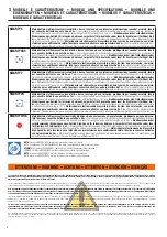
 General safety precautions 

Failure to respect the information given in this manual may cause personal injury or damage to the 

device.

This installation manual is intended for qualified personnel only.  

ROGER TECHNOLOGY cannot be held responsible for any damage or injury due to improper use or any use other the intended usage indicated in this manual. 

Installation, electrical connections and adjustments must be performed by qualified personnel, in accordance with best practices and in compliance with applicable 

regulations.

Read the instructions carefully before installing the product. Bad installation could be dangerous. 

Before installing the product, make sure it is in perfect condition: if in doubt, do not use the equipment and contact qualified personnel only.

Do not install the product in explosive areas and atmospheres: the presence of inflammable gas or fumes represents a serious safety hazard.

Before installing the motorisation device, make all the necessary structural modifications to create safety clearance and to guard or isolate all the crushing, shearing, 

trapping and general hazardous areas.

Make sure the existing structure is up to standard in terms of strength and stability.

ROGER TECHNOLOGY is not responsible for failure to observe Good Working Methods when building the frames to be motorised, or for any deformation during use.

The safety devices (photocells, safety edges, emergency stops, etc.) must be installed taking into account: applicable laws and directives, Good Working Methods, 

installation premises, system operating logic and the forces developed by the motorised door or gate.

The safety devices must protect against crushing, cutting, trapping and general danger areas of the motorised door or gate.

ROGER TECHNOLOGY declines all responsibility if component parts not compatible with safe and correct operation are fitted.

Display the signs required by law to identify hazardous areas.

Each installation must bear a visible indication of the data identifying the motorised door or gate.

An omnipolar disconnection switch with a contact opening distance of at least 3mm must be fitted on the mains supply.

Make sure that upline from the mains power supply there is a residual current circuit breaker that trips at no more than 0.03A and overcurrent cutout upstream of the 

electrical system in accordance with best practices and in compliance with applicable regulations.

When requested, connect the automation to an effective earthing system 

 that complies with current safety standards.

During installation, maintenance and repair operations, cut off the power supply before opening the cover to access the electrical parts.

The electronic parts must be handled using earthed antistatic conductive arms.

Only use original spare parts for repairing or replacing products.

The installer must supply all information concerning the automatic, manual and emergency operation of the motorised door or gate, and must provide the user with 

the operating instructions.

The packaging materials (plastic, polystyrene, etc.) should not be discarded in the environment or left within reach of children, as they are a potential source of danger.

Dispose of and recycle the packing components in accordance with the standards in force.

These instruction must be kept and forwarded to all possible future user of the system.

Declaration of Conformity

I the undersigned, as acting legal representative of the manufacturer:

Roger Technology - Via Botticelli 8, 31021 Bonisiolo di Mogliano V.to (TV)

hereby DECLARE that the appliance described hereafter:

Description: Swing gate automation

Model: serie 

SMARTY

Is conformant with the legal requisites of the following directives:

• Directive 

2014/30/EU

 (EMC Directive) and subsequent amendments;

• Directive 

2014/35/EU

 (Low Voltage Directive) and subsequent amendments;

and that all the standards and/or technical requirements indicated as follows have been applied:

EN 61000-6-3

EN 61000-6-2

EN 60335-1

EN 60335-2-103

Last two figures of year in which marking was applied  

|

  16.

Place: Mogliano V.to             Date: 30/04/2016                      Signature  


ROGER TECHNOLOGY is the exclusive proprietor holder of all rights regarding this publication.

ROGER TECHNOLOGY reserves the right to implement any modifications without prior notification. Copying, scanning or any alterations to this document are prohibited without express 

prior authorised from by ROGER TECHNOLOGY.

This instruction manual and the warnings for the installer are given in printed form and included in the box containing the product. 

The digital version of this documentation (in PDF format) and all future revisions are available from the reserved area of our website www.rogertechnology.com/B2B, in the section ‘Self 

Service’.

ROGER TECHNOLOGY CUSTOMER SERVICE: 

business hours: 

Monday to Friday 08:00 to 12:00 - 13:30 to 17:30

Telephone no:  +39 041 5937023

E-mail:  


service@rogertechnology.it

Skype:  


service_rogertechnology

Summary of Contents for SMARTY Series

Page 1: ...EMENTS POUR L INSTALLATEUR INSTRUCCIONES Y ADVERTENCIAS PARA EL INSTALADOR INSTRUÇÕES E AVISOS PARA O INSTALADOR Serie SMARTY Automazione per cancelli a battente Swing gates automations Automatisierung für Drehtore Automatisme pour portails à battant Automatismos para cancelas batientes Automações para portões de batente Istruzioni originali IS131 Rev07 04 11 2019 ...

Page 2: ...glia di 0 03 A ed una protezione di sovracorrente adeguati nell osservanza della Buona Tecnica ed in ottemperanza alle norme vigenti Quando richiesto collegare l automazione ad un efficace impianto di messa a terra eseguito come indicato dalle vigenti norme di sicurezza Durante gli interventi di installazione manutenzione e riparazione togliere l alimentazione prima di aprire il coperchio per acce...

Page 3: ...ith best practices and in compliance with applicable regulations When requested connect the automation to an effective earthing system that complies with current safety standards During installation maintenance and repair operations cut off the power supply before opening the cover to access the electrical parts The electronic parts must be handled using earthed antistatic conductive arms Only use...

Page 4: ...A vorgeschaltet ist der den geltenden Normen entspricht Falls vorgeschrieben den Antrieb an eine wirksame und den Sicherheitsnormen entsprechende Erdungsanlage anschließen Unterbrechen Sie während der Montage Wartungs oder Reparaturarbeiten die Stromzufuhr bevor Sie den Deckel für den Zugang zu den elektrischen Geräten öffnen Eingriffe an den elektronischen Geräten dürfen nur mit antistatischem ge...

Page 5: ...er s il y a en amont du réseau d alimentation un disjoncteur dont le seuil ne dépasse pas 0 03A et une protection contre la surintensité adéquats sont installés en amont de l installation électrique selon les règles de la bonne technique et conformément aux normes en vigueur Si nécessaire raccorder l automatisme à une installation efficace de mise à la terre exécutée conformément aux normes de séc...

Page 6: ...recorriente adecuados de conformidad con las prácticas de la buena técnica y las normativas vigentes Cuando sea necesario conecte la puerta o las cancelas motorizadas a una toma de tierra eficaz realizada siguiendo las normas de seguridad vigentes Durante las operaciones de instalación mantenimiento y reparación desactive la alimentación antes de abrir la tapa de acceso a los componentes eléctrico...

Page 7: ... de acordo com critérios da Boa Técnica e em conformidade com as normas em vigor Quando requerido ligar o automatismo a um apropriado sistema de colocação a terra realizado em conformidade com as normas de segurança vigentes Durante as intervenções de instalação manutenção e reparação desligar a alimentação antes de abrir a tampa para ter acesso às partes elétricas A manipulação das partes eletrón...

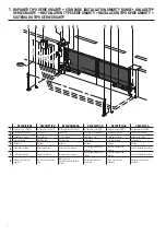
Page 8: ...ave Selector de chave 4 Lampeggiante Flashing light Blinkleuchte Clignotant Luz intermitente Lampejante 5 Antenna Antenna Antenne Antenne Antena Antena 6 Fotocellula esterna External photocell Externe Lichtschranke Cellule photoélectrique externe Barrera fotoeléctrica exterior Sensor fotoelétrico externo 7 Fotocellula interna Internal photocell Interne Lichtschranke Cellule photoélectrique interne...

Page 9: ...e gate length exceeds 2 5 m with normal wings 2 m with full wings and if its height exceeds 2 m it is recommended to use an electric lock Nach den geltenden Vorschriften und aus Sicherheitsgründen wenn das Tor 2 5 m Länge bei normalen Flügeln 2 m Länge bei vollen Flügeln und 2 m Höhe überschreitet wird empfohlen das Elektroschloss zu verwenden Aux termes de la réglementation en vigueur et aux fins...

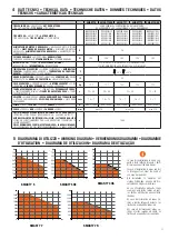
Page 10: ...tensione ad uso intensivo predisposto per encoder asso luto ideale per cancelli a battente con anta fino a 4 m Low voltage irreversible electromechanical gear motor High Speed for heavy duty use configured for use with absolute encoder and ideal for swing leaf gates with leaf lengths up to 4 m Elektromechanischer selbsthemmender Niederspannungs Antrieb High Speed für intensiven Gebrauch vorgerüste...

Page 11: ...90 s 25 40 20 40 35 50 15 25 VELOCITÀ WORKING SPEED GESCHWINDIGKEIT DER TORBEWEGUNG VITESSE DE MANOEUVRE VELOCIDAD DE MANIOBRA VELOCIDADE DE MANOBRA cm s 1 6 1 1 8 1 2 1 6 1 1 6 1 2 1 SPINTA TRUST SCHUB POUSSEE EMPUJE IMPULSO N 600 7000 600 6500 600 7000 600 6500 600 4500 CORSA TRAVEL HUB COURSE CARRERA CURSO mm max 370 max 520 max 370 CICLI DI MANOVRA GIORNO APERTURA CHIUSURA 24 ORE NON STOP OPER...

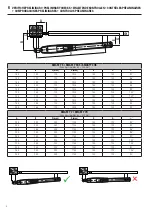
Page 12: ... 90 200 160 120 1030 100 130 92 SMARTY 7 SMARTY 7R Corsa massima Max run 520 mm A B C max D max E G α 200 200 200 1180 140 170 98 200 230 200 1180 140 170 97 200 260 200 1180 140 170 96 200 280 200 1180 140 170 95 200 300 200 1180 140 170 93 220 220 200 1180 140 170 102 220 250 200 1180 140 170 100 220 280 200 1180 140 170 93 250 200 200 1180 140 170 106 250 250 200 1180 140 170 94 6 VERIFICHEPREL...

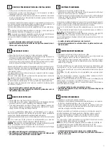
Page 13: ... Dicke berechnet Die Spitze des Kolbens muss zum Flügel gerichtet sein Den Flügel von Hand öffnen und sicherstellen dass der Kolben nicht mit dem Flügel oder dem Pfeiler zusammenstößt CONTRÔLESPRÉLIMINAIRES FR Vérifier que la structure du portail soit robuste Vérifier que les gonds soient bien graissés et que le mouvement soit fluide et régulier sur toute la course et sans frottements Toujours pré...

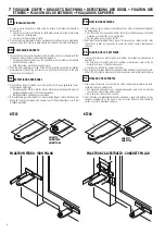
Page 14: ...R PILASTRI IN CALCESTRUZZO CONCRETE PILLAR FR FIXATION DES ÉTRIERS 1 Fixer l étrier arrière à niveau conformément aux cotes d installation indiquées au paragraphe 6 Sur les piliers en maçonnerie utiliser les étriers prédisposés pour le type de matériau avec chevilles et vis appropriées Sur les piliers en fer souder l étrier 2 Avec le portail entièrement fermé placer l étrier avant en respectant le...

Page 15: ...en dass sein Lauf regelmäßig und reibungslos erfolgt FR INSTALLATION Le piston SMARTY peut être installé indifféremment à droite ou à gauche Fixer le piston à l étrier arrière et l étrier avant en lubrifiant les points de rotation Tout en actionnant manuellement le portail vérifier que toute la course soit régulière et dépourvue de frottements ES INSTALACIÓN El pistón SMARTY puede instalarse tanto...

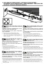
Page 16: ...Stringere con forza Tighten strongly Fig 1 1 4 2 3 Fig 2 FR Utiliser les fermoirs mécaniques intérieurs au piston comme sécurité d arrêt supplémentaire aux butées méca niques du portail ATTENTION les butées mécaniques sont desserrées à l intérieur du piston Même si elles ne sont pas utilisées elles doivent toujours être fixées Les butées mécaniques du portail en ouverture et en fermeture doivent t...

Page 17: ...nd the SMARTY gear motor tests are illustrated in the installation manual of the EDGE1 control unit Prévoir sur le réseau d alimentation un interrupteur ou un dispositif de coupure omnipolaire avec distance d ouverture des contacts égale ou supérieure à 3 mm Vérifier qu un disjoncteur différentiel avec un seuil de 0 03 A et une protection contre la surintensité adéquats sont installés en amont de ...

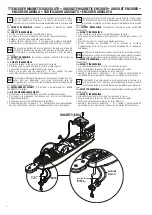
Page 18: ... calculer la position exacte du portail et ainsi après une interruption de tension ou le déblocage du portail dès la réception de la première commande la centrale récupère immédiatement la position des vantaux Pour SMARTY RÉVERSIBLE l encodeur est installé en usine par ROGER TECHNOLOGY Pour SMARTY IRRÉVERSIBLE Fixer l encodeur sur le moteur comme indiqué dans la figure Faire passer le câble indiqu...

Page 19: ... control functions work correctly Check that the obstacle detection function works correctly Check that the force limiting function prevents potentially dangerous situations in com pliance with the standard EN 12445 NOTA Utilice solo recambios originales para la reparación o la sustitución del producto El instalador debe facilitar toda la información relacionada con el funcio namiento automático m...

Page 20: ...ROGER TECHNOLOGY Via S Botticelli 8 31021 Bonisiolo di Mogliano Veneto TV ITALIA P IVA 01612340263 Tel 39 041 5937023 Fax 39 041 5937024 info rogertechnology com www rogertechnology com ...

Reviews: