20
EN
20
2
3
11
INSTALLATION
11.1
Preliminary checks
• Check that the material received is in good condition and suitable for
the application.
• Check that the operating limits of the product are not exceeded.
• Check that the site chosen for installation meets the overall space
requirements of the product and that there are no obstacles hindering
open or close manoeuvres.
• Check the concrete base for the barrier installation. The base must be
cast in accordance with proper working practices, perfectly level and
clean.
11.2
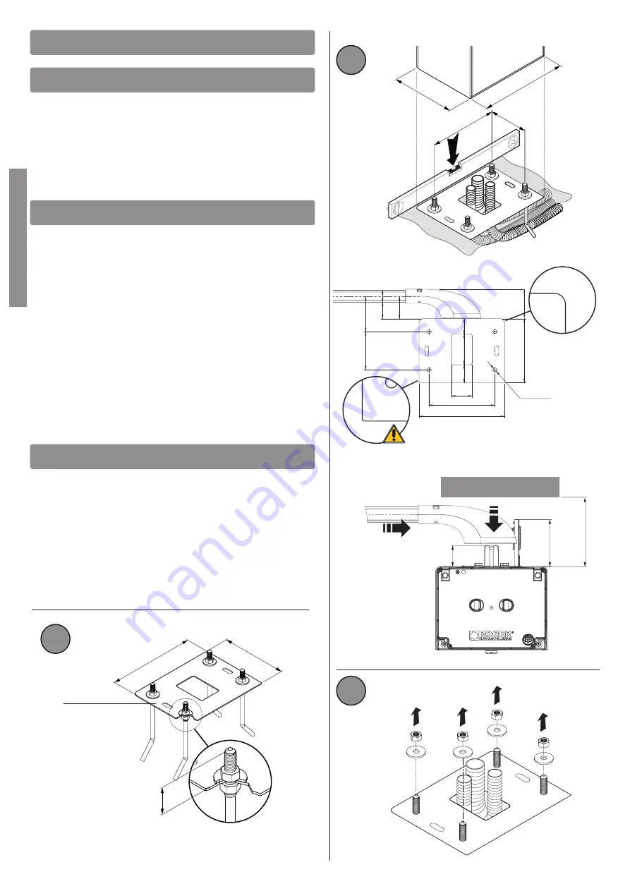
Installing base plate
The illustrations herein are indicative only. The space necessary for
fastening the automation system and the accessories may vary depending
on the overall dimensions of the installation. The installer is responsible for
determining the most suitable solution.
• Excavate a foundation pit measuring 1m x 1m x 0.4 m and fill with
concrete reinforced with steel mesh.
• Fasten the 4 anchor ties to the plate (fig. 1). N.B.: the bottom nut must
be tightened to the end of the thread on the screw so that the length Z
is at least 40 mm.
• Sink the base plate with the anchors in the centre of the foundation pit,
so that the surface is flush with the concrete and perfectly level. The
corrugated cable conduits must protrude by a few centimetres from the
centre of the plate.
PAY ATTENTION to the installation direction of the plate. See the
detailed view in fig. 2. The inspection side must be accessible from
inside the home / shop / business.
• Installation on existing surfaces. Place the base plate on the surface
and trace the positions of the fastener points. Drill the surface and fit 4
expansion anchor bolts (purchased separately).
11.3
Installing the barrier
N.B.:
the barrier is configured by default for installation on the right hand
side (viewed from the inspection hatch).
• Undo and remove the washers and nuts from the anchors on the base
plate (fig. 3).
• Open the inspection hatch, turning the key clockwise 90° (fig. 4) and
remove it.
• Place the cabinet on the plate. The anchors on the base plate must fit
through the four slots.
• Fit the washers and nuts removed previously. Move the cabinet as
necessary in the slots to adjust the position of the barrier correctly.
• Tighten the nuts securely (fig. 6).
280
210
216
125
1
280
210
Z=>40 mm
KT240
97
21
0
280
59
10
0
51
11
6
12
5
4xØ12,5
216
73
68
54
40
Lato sportello di ispezione
Inspection hatch side
53
11
8
≥
160
Summary of Contents for BI/004
Page 1: ......


