background image


Page 

16

 of 

21


[72] 

Alarm in controllers 

The output is activated for 3 minutes if any alarm is raised in 
one of PR series controllers within the subsystem (network). 

[73] 

Alarm in CPR 

The output is activated for 3 minutes if Tamper Alarm or 
Power supply alarm is raised. The function [67] operates as a 
sum of [81] and [82] functions. 

[74] 

Low battery 

The output remains activated as long as charge level of 
backup battery connected to CPR32-NET unit is low. 

[75] 

18VAC supply lost 

The output is activated after 15 minutes of 18VAC power 
supply shortage to CPR32-NET unit and remains activated 
until the power supply is restored. 

[76] 

Battery failure 

The output is activated in case of battery failure (no battery 
or internal damage of battery). If the output is activated then 
the battery must be checked by maintenance personnel. The 
output remains activated until the problem is eliminated. 

[77] 

CPR on 

The output signals that CPR32-NET is switched on by PR 
Master software. 

[78] 

CPR off 

The output signals that CPR32-NET is switched off by PR 
Master software. 

[79] 

Internal failure 

The output is activated when internal testing detects RTC 
failure, firmware memory failure or data memory error. 
Internal test is performed every 20 minutes. The output is 
activated until the failure/error is removed. 

[80] 

Buffer alarm - 
modulated 

The output is activated when the event memory buffer is full 
and remains activated until the buffer is cleared. The signal 
is modulated (1 sec. of signal/ 1 sec. of pause). 

[81] 

Tamper alarm 

The output is activated for 3 minutes if anti-sabotage 
(tamper) alarm is raised. The alarm is raised when the input 
with function [02] is activated. 

[82] 

Power supply alarm 

The output is activated for 3 minutes if problem with CPR32-
NET power supply occurs. The function [82] is a sum of [74], 
[75] and [76] functions. 

[83] 

Communication lost 

The output is activated as long as the communication with 
any PR series controller within particular subsystem 
(network) is lost. 

[84] 

Buffer alarm 

The output is activated when the event memory buffer is full 
and remains activated until the buffer is cleared. 

[85] 

Buffer prealarm 

The output is activated when the event memory buffer is 
filled in 75%. 

[86] 

Internal failure (3 
min) 

The output is activated for 3 minutes when internal testing 
detects RTC failure, firmware memory failure or data 
memory error. Internal test is started every 20 minutes. 

[87] 

Communication lost 
(3 min) 

The output is activated for 3 minutes if the communication 
with any PR series controller within particular subsystem 
(network) is lost. 

[88] 

Buffer alarm (3 min) 

The output is activated for 3 minutes when the event 
memory buffer is full. 

[89] 

Buffer prealarm (3 
min) 

The output is activated for 3 minutes when the event 
memory buffer is filled in 75%. 

Summary of Contents for CPR32-NET

Page 1: ...Roger Access Control System CPR32 NET network controller User manual Firmware version 1 0 4 or newer Hardware version 1 0 Document version Rev B ...

Page 2: ...EGRA series alarm panels 9 3 5 3 Integration with wireless door locks in SALLIS system 9 3 6 Ethernet port 9 3 7 Installation guidelines 9 4 Configuration 9 4 1 Configuration by means of web browser 9 4 2 Configuration by means of PR Master software 11 4 2 1 New subsystem with CPR32 NET 11 4 2 2 CPR32 NET options 13 4 3 CPR32 NET operation with memory cards 18 4 4 Secure communication with CPR32 N...

Page 3: ... alarm panels of INTEGRA SATEL series time synchronization with NTP server The network controller is equipped with two RS485 ports which are used for communication with access controllers and for integration with INTEGRA or SALLIS systems The communication with computer PR Master software is performed by means of Ethernet port and is secured with AES128 CBC encryption standard Events from access c...

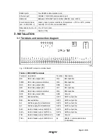
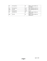
Page 4: ...l Description NC1 REL1 relay output NC IN5 IN5 input line COM1 REL1 relay common terminal IN6 IN6 input line NO1 REL1 relay output NO GND Ground NC2 REL2 relay output NC IN7 IN7 input line COM2 REL2 relay common terminal IN8 IN8 input line NO2 REL2 relay output NO GND Ground BAT Backup battery OUT1 OUT1 output line BAT Backup battery OUT2 OUT2 output line AC 18VAC supply from transformer OUT3 OUT3...

Page 5: ...ation bus controllers IN2 IN2 input line CLK RACS Clock Data comm bus GND Ground DTA RACS Clock Data comm bus IN3 IN3 input line GND Ground IN4 IN4 input line A2 RS485 2 communication bus integrations GND Ground B2 RS485 2 communication bus integrations ...

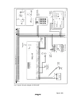
Page 6: ...Page 6 of 21 Fig 2 Typical connection diagram of CPR32 NET ...

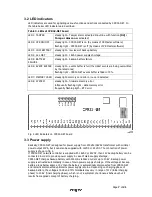
Page 7: ...quently flashing light data memory error frequently flashing ligth RTC error Fig 3 LED indicators on CPR32 NET board 3 3 Power supply Basically CPR32 NET is designed for power supply from 230VAC 18VAC transformer with minimal power output 20VA but it can also be supplied with 12VDC or 24VDC The connection of power supply is shown in fig 4 If CPR32 NET network controller is supplied with 18VAC or 2...

Page 8: ... COM contacts are shorted In case of power outage both outputs remain in the off state 3 4 3 General purpose outputs Six transistor outputs OUT1 OUT6 are available in CPR32 NET network controller All these lines are open collector type i e in the normal off state are pulled to supply plus via 5 6 kΩ resistor and when on they short to supply minus All lines can switch current up to 1A DC while volt...

Page 9: ...8 doors i e 32 doors with PR series single door controllers and 16 doors with SALLIS system door locks More information on integration with wireless door locks of SALLIS system is given in the document Integration of RACS 4 and Sallis wireless lock system Salto User manual 3 6 Ethernet port CPR32 NET is equipped with 10BaseT Ethernet port which is used for communication with computer PR Master sof...

Page 10: ...rer Note In order to connect with CPR32 NET in local area network LAN the computer must be in the same subnet In case of CPR32 NET with default IP address the IP address of computer should be 192 168 0 xxx Fig 5 CPR32 NET webpage started by means of web browser In fig 5 following configuration options are available Network In this window following parameters of CPR32 NET can be modified IP address...

Page 11: ...of PR Master software CPR32 NET acts as central unit with event buffer and Ethernet RS485 communication interface for communication with various devices in RACS 4 system including access controllers 4 2 1 New subsystem with CPR32 NET In order to create new subsystem with CPR32 NET unit and to detect access controllers it is necessary to select the option Networks in the main window of PR Master so...

Page 12: ... connected to RS485 1 bus of CPR32 NET The maximum number of single door controllers connected to CPR32 NET unit equals to 32 units Each controller connected to CPR32 NET must have different address Example of RACS 4 system consisting of two subsystem is shown in fig 8 Multiple CPR32 NET units forming multiple subsystems can operate within single RACS 4 system Each CPR32 NET unit must have differe...

Page 13: ... options by clicking CPR32 NET option in the main window of PR Master software which results in opening of the window shown in fig 9 with summary of CPR32 NET setup and top menu with following options and commands Menu Configuration Settings In the window opened by means of this option the administrator can activate deactivate power supply tests and internal tests of CPR32 NET unit as well as sele...

Page 14: ...arms are cleared in CPR32 NET unit 02 Tamper alarm Constant When the input is activated Tamper alarm is raised and consequently both the output with dedicated function 81 and LED 1 are activated 08 Set all doors to Normal mode Momentary When the input is activated then Normal Door Mode is activated at all controllers doors within subsystem network 09 Set all doors to Unlocked mode Momentary When t...

Page 15: ...ndow opened by means of this option it is possible to assign functions to CPR32 NET outputs CPR32 NET is equipped with 6 transistor outputs and 2 relay outputs Output lines can be normal or inverted type and they are configured in the same way as output lines of RACS 4 controllers The list of available functions is shown in table 5 Table 5 Output functions No Function Description 00 None Output li...

Page 16: ...error is removed 80 Buffer alarm modulated The output is activated when the event memory buffer is full and remains activated until the buffer is cleared The signal is modulated 1 sec of signal 1 sec of pause 81 Tamper alarm The output is activated for 3 minutes if anti sabotage tamper alarm is raised The alarm is raised when the input with function 02 is activated 82 Power supply alarm The output...

Page 17: ...can be entered manually or selected from the list NTP provides Coordinated Universal Time UTC therefore all time zones and daylight saving times are not included and have to be configured in CPR32 NET e g select UTC 1 00 in the field Time zone If CPR32 NET is connected in LAN then port 123 must be forwarded at router in order to enable communication of CPR32 NET with NTP If several CPR32 NET are i...

Page 18: ...2032 battery Switching between built in flash memory and flash memory card in CPR32 NET can be done by means of the PR Master option which can be accessed in CPR32 NET properties i e PR Master CPR32 NET Configuration Settings Events buffer see fig 10 Fig 10 Events buffer option 4 4 Secure communication with CPR32 NET 4 4 1 Encrypted communication The communication between PR Master software and CP...

Page 19: ...figured by means of CPR32 NET webpage in the menu Networks in the field Dedicated host where IP address of such authorized computer can be entered 4 5 Full memory reset of CPR32 NET Full memory reset of CPR32 NET results in erasing of current settings and restoring of default settings Reset procedure Switch off CPR32 NET power supply Remove connections to CLK and DTA terminals if applicable Connec...

Page 20: ... 1 port 1 Connect CPR32 NET to computer with Roger CLD software by means of RS485 communication interface e g UT 2USB or RUD 1 RS485 1 terminals of CPR32 NET must be connected respectively to RS485 terminals of communication interface 2 Start Roger CLD software see fig 13 3 Select serial port COMx with connected communication interface UT 2USB or RUD 1 4 Select frg firmware file by means of Open F...

Page 21: ...er equipment to the designated collection points of electric and electronic waste For detailed information on recycling contact your local authorities waste disposal company or point of purchase Separate collection and recycling of this type of waste contributes to the protection of the natural resources and is safe to health and the environment Weight of the equipment is specified in the document...

Reviews: