HRT82PB Installation Guide Rev.C.doc
2016-10-10
2/5
1.
I
NTRODUCTION
This manual contains minimum information that is necessary to properly install device.
2.
D
ESCRIPTION AND SPECIFICATION
HRT82PB push button panel can be connected to controller inputs/outputs and due to its universal
construction it can be used both with Roger and third party devices equipped with NO inputs,
transistor (open collector) outputs and/or relay outputs. The panel enables activation of various
functionalities and states with its buttons.
HRT82PB front panel includes four LED indicators and four push buttons
Table 1. Specification
Supply voltage (for LED
indicators)
Nominal 12VDC, min./max. range 10-15VDC
Environmental class
(acc. to EN 50131-1)
Class II, indoor general conditions, temperature: -10°C- +50°C, relative
humidity: 10 to 95% (no condensation)
IP code
IP41
Dimensions HxWxD
85 x 85 x 26 mm
Weight
~ 100g
Certificates
CE
3.
I
NSTALLATION
3.1 Terminals and connection diagram
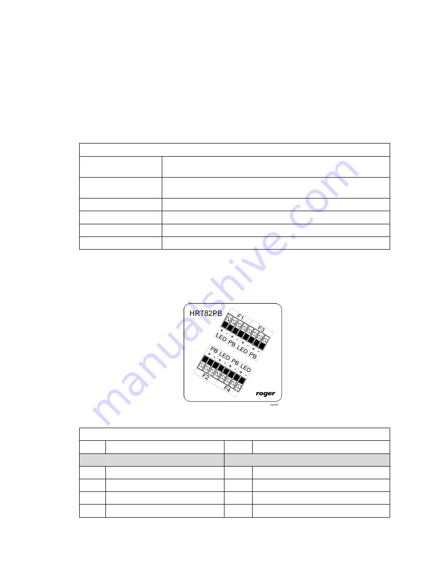
Fig. 1 HRT82PB push button panel
Table 2. HRT82PB terminals
Term. Description
Term. Description
F1
F2
LED+ F1 LED + terminal, +12VDC
LED+
F2 LED + terminal, +12VDC
LED-
F1 LED – terminal, GND
LED-
F2 LED – terminal, GND
PB+
F1 button contact (SPST-NO)
PB+
F2 button contact (SPST-NO)
PB-
F1 button contact (SPST-NO)
PB-
F2 button contact (SPST-NO)


