HRT82PB Installation Guide Rev.C.doc
2016-10-10
3/5
F3
F4
LED+ F3 LED + terminal, +12VDC
LED+
F4 LED + terminal, +12VDC
LED-
F3 LED – terminal, GND
LED-
F4 LED – terminal, GND
PB+
F3 button contact (SPST-NO)
PB+
F4 button contact (SPST-NO)
PB-
F3 button contact (SPST-NO)
PB-
F4 button contact (SPST-NO)
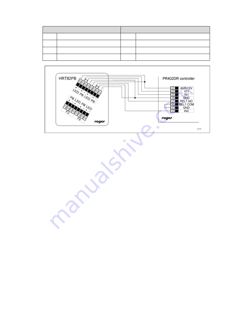
Fig. 2 Example of connection to PR402DR controller
3.2 Front panel
LED indicators
In the area of each button there is located red LED indicator. Each indicator can be switched on by
supplying 12VDC from external source. Indicator is controlled by means of transistor open collector
type output or by means of relay output (see fig. 2). Roger controller outputs can be programmed
by assigning available functions. In practical applications, indicator is logically associated with
button in order to signal that the button was used and adequate function or state was activated.
Push buttons
HRT82PB panel is equipped with four push buttons. Each SPST-NO type button offers isolated
NO/0,125A/48VDC contact which can be used to control the input of controller or low power load
point (up to 5VA). Roger controller inputs can be programmed by assigning available functions.
3.3 Wall mounting and installation guidelines
HRT82PB consists of front panel and base which are factory assembled and require manual
disassembly prior to installation according to fig. 3.
Installation guidelines
Install device on wall far from sources of heat and moisture
It is recommended to install device on Ø60mm flush mounting box
All electric connections must be made with power supply switched off
Run connection wires through hole in device base and then connect wires to screw terminals
Front panel can be regularly cleaned with wet cloth and mild detergent. Do not clean by means
of abrasive materials and strong cleaners like alcohols, solvents, etc.
Damages resulting from improper maintenance or use are not covered by warranty


