MCX2D Operating Manual
12.11.2020
11/13
DEV, PWR1
Parameter defines any text or comment which corresponds to the
device/object. It is later displayed in VISO program.
Input comments
DC1, DR1, DC2, DR2
Parameter defines any text or comment which corresponds to the
object. It is later displayed in VISO program.
Output comments
LCK1, BELL1, LCK2, BELL2
Parameter defines any text or comment which corresponds to the
object. It is later displayed in VISO program.
Memory reset procedure and manual addressing
Memory reset procedure resets all settings to factory default ones and it enables to manually configure the
address on RS485 bus.
1. Remove all connections from LCK1 and DC1 lines.
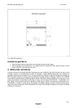
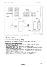
2. Place jumper on MEM contacts (fig. 2).
3. Connect LCK1 and DC1 lines.
4. Restart the device by pressing RST button and ACL LED indicator will pulsate.
5. Disconnect LCK1 and DC1 lines and RUN LED indicator will pulsate. The number of consecutive
flashes will correspond to expander’s address on RS485 bus.
6. Press RST button in a certain moment to select certain address (table 5) or press RST button after 16
flashes when ACL and RUN LED indicators are switched on to select default ID=100 address.
7. Remove jumper from MEM contacts and restart the device.
Table 5. RS485 address encoding
Number of RUN LED
flashes
RS485 address
Number of RUN LED
flashes
RS485 address
1
101
9
109
2
102
10
110
3
103
11
111
4
104
12
112
5
105
13
113
6
106
14
114
7
107
15
115
8
108
16
100
Example:
In order to select ID=105 address within memory reset procedure, press RST button after 5 flashes of RUN
LED indicator.
High level configuration (VISO)
The purpose of high level configuration is to define logical functioning of the expander which communicates
with the MC16 access controller and it depends on applied scenario of operation. The example of access
control system configuration is given in AN006 application note which is available at
5.
F
IRMWARE UPDATE
The update requires connection of expander to computer with RUD-1 interface (fig. 8) and starting
RogerVDM software. The latest firmware file is available at
Firmware update procedure:
1. Connect the device to RUD-1 interface (fig. 8) and connect the RUD-
1 to computer’s USB port.

