MCX2D Operating Manual
12.11.2020
3/13
Backup battery
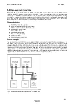
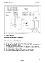
MCX2D enables battery charging with 0.3A, 0.6A or 0.9A current up to the level of voltage supplied to the
expander (nominal 13.8VDC). The current is selected with jumpers (fig. 2). When battery voltage drops to
approximately 10V then it is disconnected from expander. The battery is reconnected when the 13.8V
supply to expander is restored. In order to ensure battery charging up to 80% level within 24h (according to
EN 60839 standard) following current settings must be applied:
300mA for 7Ah battery
600mA for 17Ah battery
900mA for 24Ah battery
RS485 bus
MCX2D is an addressable device connected to RS485 communication bus of the MC16 controller. At the
same time the expander distributes the bus to MCT terminals at each door. The expander can be operated
with default ID=100 address or it can be assigned with the address in range of 101-115. All devices on
RS485 bus of MC16 controller including MCX expanders and MCT terminals must have unique addresses
in range of 100-115. MCX2D is addressed within low level configuration by means of RogerVDM software or
manually within memory reset procedure.
In most cases communication works with any cable type (standard telephone cable, shielded or unshielded
twisted pair etc.) but the recommended cable is unshielded twisted pair (U/UTP cat.5). Shielded cables
should be limited to installations subject to strong electromagnetic interferences. The RS485 communication
standard used in the RACS 5 system guarantees proper communication in a distance of up to 1200 meters
as well as high resistance to interferences.
Note: Do not use more than single pair in UTP cable for RS485 communication bus.
LED indicators
Expanders are equipped with LED indicators which are used to signal integral functions. According to further
mentioned procedures, the service mode is started by placing jumper on MEM contacts and restarting the
expander.
Table 1. LED indicators
Indicator
Colour
Integral functions
ACL
Red
In normal mode the LED indicates backup power supply from battery
instead of PSU.
RUN
Red
Single pulse every 4 sec. : normal mode
Quick pulsing: service mode
Slow pulsing (0.5s/0.5s): No communication with controller
Very slow pulsing (1s/1s): Configuration memory error
In case of Memory reset this LED is used for manual addressing.
TXD
Red
LED indicates data transmission to controller
RXD
Green
LED indicates data receiving from controller
VDR, TML,
VOUT, AUX
Green
LED indicates voltage at particular output.
LCK
Red
LED is on when corresponding LCK output is switched on.
Inputs
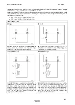
Expander offers DC and DR parametric inputs of NO, NC, 3EOL/DW/NO and 3EOL/DW/NC type. Input
types and electric parameters such as response time and parametric resistors are defined within low level

