background image

MCX2D Operating Manual 


12.11.2020 


5/13 


Parametric resistors 

The same values of parametric resistors are used for all inputs i.e. 1kΩ; 1,2kΩ; 1,5kΩ; 1,8kΩ; 2,2kΩ; 2,7kΩ; 
3,3kΩ; 3,9kΩ; 4,7kΩ; 5,6kΩ; 6,8kΩ; 8,2kΩ; 10kΩ; 12kΩ. In case of 3EOL/DW (Double Wiring) input type, 
Alarm A resistor defines a value of resistor used to detect triggering of the first input while Alarm B resistor 
defines a  value of resistor used to detect triggering of the second input. Alarm A resistor value must differ 
from value of Alarm B resistor at least by three positions in the list above. Total resistance of wire used to 
connect contacts to input should not exceed 100 Ω. Default values of parametric resistors: 


Alarm A = 2,2 kΩ 


Alarm B = 5,6 kΩ 

Response time 

Response time parameter defines minimal impulse time on the input which triggers the input. Each input can 
be configured individually in range of 50 to 5000 ms within low level configuration (RogerVDM). 

Transistor outputs 

Expander offers LCK and BELL transistor outputs. Electric parameters such as polarity are configured within 
low level configuration (RogerVDM). Function are assigned to outputs within high level configuration (VISO). 
Multiple functions with different priorities can be assigned to the same output at the same time. 
In  standard  scenario  of  door  control,  LCK  outputs  are  dedicated  to  control  door  locks  while  BELL  outputs 
are  dedicated  to  control  alarm signalling  devices  and/or  door  bells.  In  standard  scenario  of  operation  both 
LCK and BELL outputs do not require low level configuration. 

Power supply outputs 

Expander  offers  6  outputs  in  order  to  provide  power  supply  to  access  controller,  terminals,  door  lock  and 
other external devices. 

VDR outputs 

VDR  power  supply  output  is  dedicated  to supply  door  lock,  alarm  signalling  device  and  other  door  related 
devices. The terminal VDR+ is protected with 1.0A electronic fuse. The terminal VDR- is internally shorted to 
ground (GND). Green LED indicator is located at the VDR+ terminal to signal voltage at the output. 

TML outputs 

TML power supply output is dedicated to supply readers at door. The terminal TML+ is protected with 0.2A 
electronic  fuse  .  The  terminal  TML-  is  internally  shorted  to  ground.  Green  LED  indicator  is  located  at  the 
TML+ terminal to signal voltage at the output. 

VOUT output 

VOUT power supply output is dedicated to supply additional electronic modules and it can be also used to 
supply  connected  access  controller.  The  terminal  VOUT+  is  protected  with  0.2A  electronic  fuse  .  The 
terminal  VOUT-  is  internally  shorted  to  ground.  Green  LED  indicator  is  located  at  the  VOUT+  terminal  to 
signal voltage at the output. 

Note: If MC16 access controller is supplied from the expander then it cannot be at the same time supplied 
by own PSU and it cannot operate with own backup battery. 

AUX output 

AUX  power  supply  output  is  dedicated  to  supply  optional  electronic  modules.  The  terminal  AUX+  is 
protected with 0.2A electronic fuse. The terminal AUX- is internally shorted to ground. Green LED indicator 
is located at the AUX+ terminal to signal voltage at the output. 

2.


I

NSTALLATION


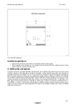
Each expander is equipped with a holder for installation on DIN35 rail. Therefore expanders can be installed 
in ME type enclosures equipped with such rail. Alternatively, expanders can also be mounted using screws 
and holes on expander board. It is recommended to install the expander in the same enclosure as PSU. The 
cross  section  of  power  supply  wires  must  be  adequate  as  to  avoid  voltage  drop  greater  than  200mV  for 
rated  load.  It  is  recommended  to use  cables  with  minimal  1mm

2

  cross  section  and  maximal  30  cm  length. 

Such cables are offered with PSxD series power supply units. 
 

Summary of Contents for MCX2D

Page 1: ...Roger Access Control System MCX2D Operating Manual Product version 1 0 Firmware version 1 1 14 or newer Document version Rev H ...

Page 2: ...ic EOL inputs 4 transistor outputs 6 power supply outputs Backup battery charging RS485 interface Removable screw terminals Power supply The expander requires 13 8VDC power supply and it is recommended to apply PS2D power supply unit for that purpose Due to relatively high current between expander and PSU all connections should be made using possibly short cables with adequate cross sections PSxD ...

Page 3: ... recommended cable is unshielded twisted pair U UTP cat 5 Shielded cables should be limited to installations subject to strong electromagnetic interferences The RS485 communication standard used in the RACS 5 system guarantees proper communication in a distance of up to 1200 meters as well as high resistance to interferences Note Do not use more than single pair in UTP cable for RS485 communicatio...

Page 4: ... is caused by CA contacts closing NC input can be in normal or in triggered state In normal state CA contacts are closed Input triggering is caused by CA contacts opening 3EOL DW NO input 3EOL DW NC input 3EOL DW NO input is operated in such way that CA contacts closing is interpreted as triggering of the first input while CB closing is interpreted as triggering of the second input In VISO softwar...

Page 5: ...cated to supply door lock alarm signalling device and other door related devices The terminal VDR is protected with 1 0A electronic fuse The terminal VDR is internally shorted to ground GND Green LED indicator is located at the VDR terminal to signal voltage at the output TML outputs TML power supply output is dedicated to supply readers at door The terminal TML is protected with 0 2A electronic f...

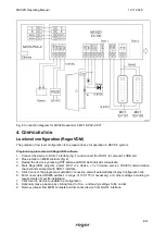
Page 6: ...0 2A output power supply to controller A B RS485 bus to controller Ax Bx RS485 bus to readers TMLx TMLx 13 8VDC 0 2A output power supply to readers VDRx VDRx 13 8VDC 1 0A output power supply to door lock LCKx 15VDC 1A transistor output line door lock BELLx 15VDC 1A transistor output line alarm signalling device DCx Input line door contact DRx Input line exit button x symbol corresponds to the numb...

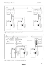
Page 7: ...16 access controller fig 5 In such scenario the maximal number of expanders operated by MC16 controller depends on its type and it is limited by available range of addresses ID 100 115 on RS485 bus of MC16 controller where all MCX and MCT devices must have unique addresses For example in case of read in out doors it is possible to control max 6 doors in such setup as MC16 PAC 6 3 x MCX2D 12 x MCT ...

Page 8: ...MCX2D Operating Manual 12 11 2020 8 13 Fig 4 Scenario of operation with MC16 PAC 2 KITs Fig 5 Scenario of operation with multiple MCX2D expanders ...

Page 9: ...essing RST button and RUN LED indicator will pulsate 4 Start RogerVDM program select MCX v1 x device v1 x firmware version RS485 communication channel and serial port with RUD 1 interface 5 Click Connect the program will establish connection and will automatically display Configuration tab 6 Enter unoccupied RS485 address in range of 100 115 if necessary and other settings according to requirement...

Page 10: ...RS485 bus Range 4 16 ASCII characters Input types DC1 DR1 DC2 DR2 Parameter defines input type Range 1 NO 2 NC 3 EOL NO 4 EOL NC 5 2EOL NO 6 2EOL NC 7 3EOL NO 8 3EOL NC 9 3EOL DW NO 10 3EOL DW NC Default value for DC is 2 NC Default value for DR is 1 NO Parametric EOL input resistances Tamper Alarm A Alarm B Ohm Parameter defines resistor for parametric EOL inputs Input response times DC1 DR1 DC2 ...

Page 11: ...in moment to select certain address table 5 or press RST button after 16 flashes when ACL and RUN LED indicators are switched on to select default ID 100 address 7 Remove jumper from MEM contacts and restart the device Table 5 RS485 address encoding Number of RUN LED flashes RS485 address Number of RUN LED flashes RS485 address 1 101 9 109 2 102 10 110 3 103 11 111 4 104 12 112 5 105 13 113 6 106 ...

Page 12: ...ttery connected 11 15 VDC no backup battery Current consumption average MCX2D expander 50mA MCX2D expander with maximal load at power outputs and maximal battery charging current 3 5A Battery charging current Configurable 0 3A 0 6A 0 9A Inputs Four DCx DRx parametric inputs Transistor outputs Four LCKx BELLx outputs each with 15V 1A DC max load Power supply outputs Two 13 8VDC 0 2A outputs VOUT AU...

Page 13: ...uct This symbol placed on a product or packaging indicates that the product should not be disposed of with other wastes as this may have a negative impact on the environment and health The user is obliged to deliver equipment to the designated collection points of electric and electronic waste For detailed information on recycling contact your local authorities waste disposal company or point of p...

Reviews: