background image

RWL-1-SL Operating Manual.doc 


2021-12-20 


12/13 


time lock switches into 

Office mode

. If the lock is in the 

Office mode

 then with the single use of a card 

with 

Office mode

 authorisation lock terminates 

Office mode

Memory reset 

Memory reset erases all programmed card and restores factory configuration settings. After reset the 

locks operates with 50 users list and reads card serial number (CSN). In order to perform memory 
reset procedure proceed with following steps: 

·


Remove jumper from the MEM pins (if applicable). 

·


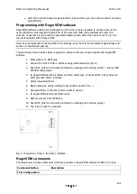
Short RST pins for a moment preferably by placing and removing jumper. 

·


When acoustic signalization is started place jumper on MEM pins and the devices shall 
confirm memory reset with 2 acoustics beeps. 

·


Read any proximity card and it shall be new ADD programming card. 

·


Read any proximity card and it shall be new DEL programming card. 

·


Wait for 3 acoustic beeps. The lock shall restore default factory settings and shall switch to 
normal operation. 

I

NSTALLATION


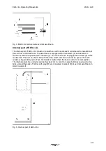
The lock is designed for installation in door with 38 to 55mm thickness and with 72mm handle 
spacing. Prior to installation make sure that door cylinder is long enough. 

Lock installation 

·


Make holes in door using drilling template In case of non-rebated door it might be 
necessary to use metal plate. Both, drilling template and metal plate are included in the 
factory new set. 

·


Install mortise lock in such a way that marks which specify proper location of handle pin 
will be aligned (fig. 6). Lead K and L groups of wires through top hole to external 

escutcheon. 

·


Install handle pin (2 parts) in mortise lock (with carvings towards lock).  

·


Optionally install external door contact (e.g. reed relay) and connect it to F group of wires 
(fig. 3). 

·


Lead battery wires and knob switch detector (fig. 5 pos. I and M) through bottom hole and 
then connect the groups of wires. 

·


Install batteries (4xAA) in the pack and then insert into internal escutcheon. 

·


Mount escutcheons and verify if the internal handle controls the cylinder and metal key can 
open the door. 

Note: Ensure access to metal key to enable emergency opening of the door. 

Specification 

Parameter 

Value 

Power supply 

4 x AA (LR06) alkaline batteries  

Battery life 

Approx. 2 years with 10 entries per day 

Door thickness 

38 – 55 mm 

Handle spacing 

72 mm 

Built-in card reader 

ISO/IEC 14443A MIFARE®  

Environmental class          

Class I, indoor general conditions, temperature: +5°C to +40°C, 

Summary of Contents for RWL-1-SL

Page 1: ...Roger Access Control System RWL 1 SL Standalone Door Lock Operating Manual Firmware version 1 1 Document version Rev A ...

Page 2: ... electronic module couples the external handle with deadbolt and latch to enable door opening When the door is closed then the deadbolt is relocked automatically in order to protect door against unauthorized opening The RWL 1 SL lock can be optionally equipped with door cylinder and then be opened from the outside with traditional metal key The RWL 1 SL is equipped with knob switch position detect...

Page 3: ...led room The escutcheon includes card reader A and hole for door cylinder G which can be used for emergency door opening with mechanical key The electronic module which is located inside the escutcheon includes service pins B and programming pins C Wires with larger plug D are used to connect the electronic module with mortise lock and wires with smaller plug E are used to connect the module with ...

Page 4: ...its status using cable with connector I The connector can be plugged into socket K at the mortise lock The door can be locked with the knob switch and then it cannot be opened from the outside using proximity card When the handle is twisted then the knob reverts to normal position The internal escutcheon includes also battery pack J In order to replace batteries unscrew two top bolts and pull the ...

Page 5: ...tronic module External handle is coupled momentary whenever access is granted When the RWL 1 SL is operated in Office mode then external handle is coupled permanently Handle spacing i e distance from handle to cylinder in the mortise lock equals to 72mm Fig 6 Mortise lock Door cylinder RWL 1 SL lock is adapted to door cylinder installation Such cylinder enables emergency door opening from the outs...

Page 6: ...alone Access Control The lock grants access for cards stored in its memory Up to 100 cards can be defined and stored in lock s memory Each card can be authorised for momentary door opening option Normal access and or to open the door for unlimited time option Office access If the card is authorized for Normal access then it opens the lock for the time specified by the parameter Lock pulse If the c...

Page 7: ...red with 2 programming cards ADD card and DEL card Lock pulse by default is set to 2 sec while built in RFID reader is configured to read card serial numbers CSN Factory cards Label Name Authorization ADD ADD programming card New card adding to the lock DEL DEL programming card Card deleting from the lock Configuration recovery from the lock In some circumstances it might be required to recover th...

Page 8: ...d to program user s Main card Read second card to program user s Backup card Wait till 3 acoustic beeps are generated by lock and then you can continue with more cards programming Example Programming of user with Office access Read ADD programming card twice Read first card to program user s Main card Read second card to program user s Backup card Wait till 3 acoustic beeps are generated by lock a...

Page 9: ... to configure the lock using computer and RogerVDM software 1 Place jumper on MEM pins 2 Connect the lock to RUD 1 interface using dedicated cable fig 6 3 Short RST pins for a moment preferably by placing and removing jumper Orange LED SYSTEM shall pulsate 4 In RogerVDM select Device New and then select type of device RWL 1 SL and serial COM port with RUD 1 interface 5 Select required settings 6 M...

Page 10: ...onfirmed with short acoustic beep Default value Yes LED SYSTEM pulsing when card close to the reader When option is set then orange LED SYSTEM pulses whenever card is detected near the reader Default value No Battery low level signalisation When option is set then lock signals low battery level by orange LED SYSTEM indicator pulsing and series of 5 acoustic beeps after card reading Default value Y...

Page 11: ... value 0 Application ID The parameter Application ID AID is located in card s MAD sector and it specifies the sector where programmable card number PCN is stored if the Sector type see above is configured as MAD Default value 5156 Roger AID Block ID The parameter specifies the block number where programmable card number PCN is stored in a particular sector of card s memory For sectors 0 31 blocks ...

Page 12: ...installation make sure that door cylinder is long enough Lock installation Make holes in door using drilling template In case of non rebated door it might be necessary to use metal plate Both drilling template and metal plate are included in the factory new set Install mortise lock in such a way that marks which specify proper location of handle pin will be aligned fig 6 Lead K and L groups of wir...

Page 13: ... of the product This symbol placed on a product or packaging indicates that the product should not be disposed of with other wastes as this may have a negative impact on the environment and health The user is obliged to deliver equipment to the designated collection points of electric and electronic waste For detailed information on recycling contact your local authorities waste disposal company o...

Reviews: