background image

SL1000A v3.1 Rev. A EN 

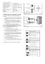
Transistor outputs 

150mA/15V DC 

Anti-tamper protection 

NC contact, 50mA/24V 

Operating temperature 

-25°..+60° 

Relative humidity 

10-95% (non-condensing) 

IP Code 

IP30 

Dimensions (W x H x D) 

68X104X23 

Weight Approx. 

490g 

Certificates CE 


SL1000A code lock configuration example 

It is assumed that the lock will perform the following 

functions: 


The RELAY output will work in a monostable mode 

with triggering time of 10 sec and will be used for door 

unlocking 


The AUX output will operate in the bistable mode 

and will be used for re-arming of an alarm system 


The PREAL. output should indicate PREALARM and 

DURESS alarms 


code re-programming should be allowed 

In order to prepare the SL1000A to performing the tasks 

defined, the 

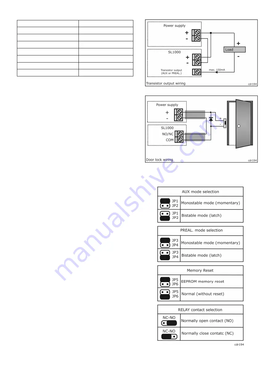
EEPROM Memory Reset

 procedure should be 

carried out according to the following scheme:   


Switch power off; 


Move the jumper from J6 to J5 position; 


Put jumpers on J2 and J4 contacts (RELAY output: 

monostable, 

The AUX output: 

bistable).


Put the NO/NC jumper in the NO position 


Switch power on, the lock will be signaling that the 

EEPROM memory has been cleared by generating short 

acoustic signals (*  *  *… ); 


move the jumper from J5 to J6 position; 


Wait until the acoustic signal is generated:   ** ** 

(two series of two signals) 


Enter five digits for C1-C5 settings: [11010] 


Wait until the lock generates three acoustic signals 

(***) 

 
After this step the lock is prepared to normal operation.  


Summary of Contents for SL1000A

Page 1: ...mands codes Each of these outputs can operate in one of two modes monostable or bistable Selection of the RELAY and AUX outputs operating modes is performed using jumpers The monostable momentary state An output operating in this mode is normally off By using Command 3 or Command 6 the output triggers for the time set by the C4C5 setting After this the output automatically switches back to the off...

Page 2: ...al permission which is granted using the Command 4 Lock commands The lock generates a different acoustic signal for the three stages of entering a command one short signal indicates that a key has been pressed two series of two signals indicate that a part of a command has been entered properly and the system waits for the remaining part a series of three signals indicates that a command has been ...

Page 3: ... for which the monostable output is triggered C4C5 01 99 sec Entering the C5 digit ends the lock configuration After this step the settings are saved in memory After configuration is complete the lock codes have the following default values Master Code MC MC 1234 Vault Code VC VC 9999 Door Code DC DC 1111 Close Code CC CC 2222 When during the process of entering C1 C5 settings an error occurs due ...

Page 4: ...indicate PREALARM and DURESS alarms code re programming should be allowed In order to prepare the SL1000A to performing the tasks defined the EEPROM Memory Reset procedure should be carried out according to the following scheme Switch power off Move the jumper from J6 to J5 position Put jumpers on J2 and J4 contacts RELAY output monostable The AUX output bistable Put the NO NC jumper in the NO pos...

Reviews: