XM-2DR Operating Manual.doc
Page
3
of
7
2.
I
NSTALLATION
2.1 Terminals and connection diagram
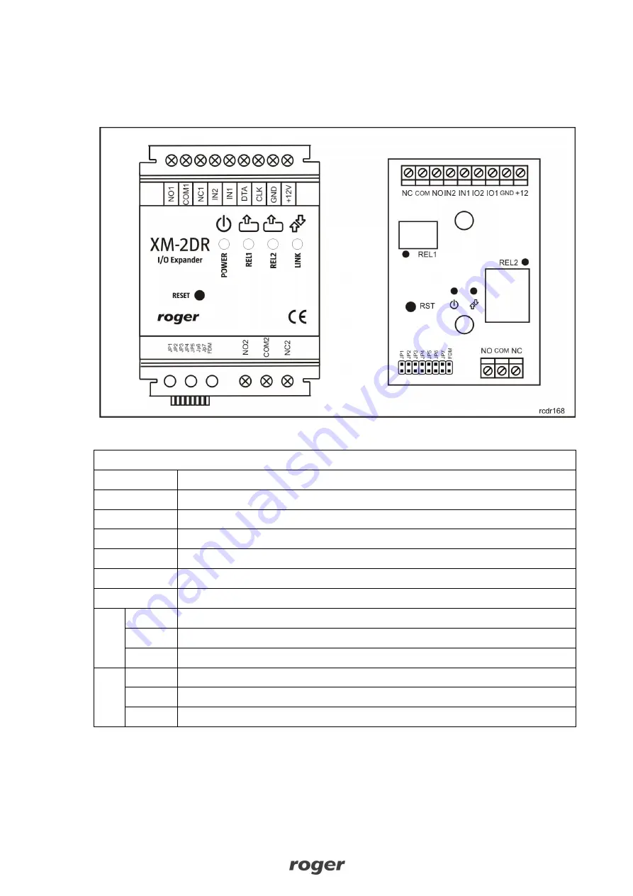
Fig. 1 Both versions of XM-2DR module
Table 2. XM-2DR terminals
Terminal
Description
+12V
Positive power supply contact, 12V DC
GND
Ground
IO1/CLK
RACS Clock & Data interface, line CLOCK
IO2/DTA
RACS Clock & Data interface, line DATA
IN1
IN1 input line
IN2
IN2 input line
RE
L1
NO
REL1 relay output, contact normally opened
COM
REL1 relay output, common terminal
NC
REL1 relay output, contact normally closed
RE
L2
NO
REL2 relay output, contact normally opened
COM
REL2 relay output, common terminal
NC
REL2 relay output, contact normally closed
In the fig. 2 there is shown connection diagram for XM-2DR and PR402DR access controller. The
communication is performed by means of RACS Clock&Data bus.


