24
2.4. Location
The unit should be installed in a well-ventilated location, free from excessive dust. Do not
install in an area where chlorine gas, hydrogen sulfide gas, sulfur dioxide gas, highly
concentrated ozone, or any other toxic, corrosive or flammable gasses are present. It is
important to provide a source of clean intake air.
Any contaminates in the atmosphere
will be compressed with the air.
The compressor must be protected against freezing and excessive ambient
temperatures. It is equipped with freeze protection, but it must be attached to an
energized source of 120VAC power to function (located on side of compressor near
external Diesel tank connections, see
Figure 6B/6C
). The unit should be in a position
that prevents the HMI, on the end of the compressor, from being exposed to direct
sunlight.
The doors open fully and can be latched open. For ease of maintenance provide ample
clearance around the compressor. If possible, overhead clearance for lifting apparatus
should be available, per the drawing in
Chapter 2.2
. The minimum recommended
service clearances are generally the width of the doors themselves. Keep items such as
external fuel vessels and receiver tanks far enough away that the doors can open fully
and be latched in their fully open position.
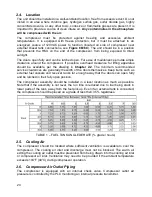
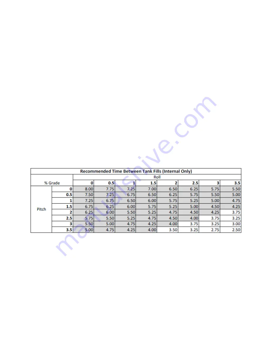
The compressor assembly should be installed in a level location as much as possible.
Note that if the assembly is not level, the run time is reduced due to fuel being stuck in
lower parts of the tank, away from the fuel pick up. Even if an external tank is connected,
the compressor should be placed on a grade of less than 3.5% regardless.
TABLE 1 – FUEL TANK ANGLE DERATE (% grade / hours)
2.5. Cooling Air
The compressor should be located where sufficient ventilation is available to cool the
compressor. The cooling air inlet and discharge must not be blocked. The warm air
exiting the cooling air outlet must be prevented from being drawn into the cooling air inlet
or compressor air inlet. Ventilation may need to be provided if the ambient temperature
exceeds 104°F (40°C) during compressor operation.
2.6. Compressor Air Outlet Piping
The compressor is equipped with an internal check valve. Compressor outlet air
pressure is controlled by the PLC monitoring an internal pressure transmitter.


