background image

 40 

7.3.  Long-term Storage 

NOTICE: 

  If an engine is not used, oil can run off the following parts that normally receive 

lubrication: cylinder walls, piston rings, main bearings, connecting rod bearings, 
crankshaft and gears. This lack of lubricant allows corrosion to begin to appear 
on the metal. This condition is worse in areas of high humidity. When the engine 
is started again, metal to metal contact will cause wear before the surfaces 
receive  oil. To minimize this wear, use the starter to turn the engine with the 
throttle in the FUEL OFF position. When oil pressure is shown on the pressure 
gauge,  start the engine.  See CAT publication “SEBU9106-14”  section  Product 
Storage for more information. 

a.  Stop the unit and add a vapor phase corrosion inhibitor oil additive. 

b.  Add VCI oil to the engine oil. The volume of VCI oil should be three to four percent by 

volume. 

c.  Run the compressor unloaded 10 minutes. 

d.  Remove the air filter element for the engine. Turn the engine at cranking speed with 

the throttle control in FUEL OFF position. Use a sprayer to add a mixture of  50 
percent VCI oil and 50 percent engine oil into the air inlet or turbocharger inlet. 

e.  Stop the compressor. 

f.  Use a sprayer to apply a mixture of 50 percent VCI oil and 50 percent crankcase oil 

into the exhaust openings. The minimum application rate for the oil mixture is 5.5 mL 
per L (3 fluid ounces  per 1000 cu in)  of engine displacement  (18  liters of 
displacement = 54fl oz of solution). Seal the exhaust pipe and seal any drain holes in 
the muffler. 

g.  Install pipe plug or cap on air outlet pipe. 

h.  Remove the fuel  from the  secondary fuel filter housing. Alternately, empty and 

reinstall the spin-on fuel filter element in order to remove any dirt and water. Drain 
any sleeve metering fuel pump. Clean the primary fuel filter. Fill with calibration fluid 
or kerosene. Install the  primary fuel filter and operate the  priming pump. This 
procedure will send clean fuel to the secondary filter and the engine. 

i.  Open the fuel tank drain valve in order to drain any water and dirt from the fuel tank. 

There are also clean out ports located in various locations on both tanks.  Apply  a 
spray of calibration fluid or kerosene at the rate of 30 mL per 30 L (1 oz per 7.50 gal 
US) of fuel tank capacity in order to prevent rust in the fuel tank. Add 0.15 mL per L 
(.02 oz per 1 gal  US) of commercial biocide such as Biobor JF to the fuel. Apply a 
small amount of oil to the threads on the fuel tank filler neck and install the cap. Seal 
all openings to the tank in order to prevent evaporation of the fuel and as a 
preservative. 

j.  Remove the fuel nozzles. Apply 30 mL (1 oz) of the mixture of oils (50 percent VCI oil 

and 50 percent engine oil) into each cylinder. Use a bar or a turning tool in order to 
turn over the engine slowly. This procedure puts the oil on the cylinder walls. Install 
all fuel nozzles or spark plugs and tighten to the correct torque. 

k.  Spray a thin amount of a mixture of 50 percent VCI oil and 50 percent engine oil onto 

the following components: flywheel, ring gear teeth and starter pinion. Install the 
covers in order to prevent evaporation of the vapors from the VCI oil. 

Summary of Contents for GPKD-1550-H

Page 1: ...OMPRESSORS OIL FREE TWO STAGE MODEL GPKD 1550 H SERIAL 1806119004 1806119033 INSTRUCTION MANUAL GPKD 1550 H CATERPILLAR C18 TIER 4 FINAL 1550 CFM KOBELCO is the international trademark found on all pr...

Page 2: ...2 THIS PAGE LEFT BLANK...

Page 3: ...uirements of OSHA 29 CFR 1910 or FDA 21 CFR 178 3570 4 Do not allow flammable toxic or corrosive gases to enter the air inlet system or electrical devices 5 Never attempt to work on compressor or remo...

Page 4: ...Cooling Air 24 2 6 Compressor Air Outlet Piping 24 2 7 Air Receiver 26 2 8 Wiring 27 3 Start Up 28 3 1 Pre start Checks 28 3 2 Initial Start up 30 4 Operating Instructions 30 4 1 Starting the Compress...

Page 5: ...and Stored Units 39 7 1 Standby Units 39 7 2 Short term Storage 39 7 3 Long term Storage 40 8 Typical Operating Conditions 41 Operating Temperatures and Pressures 41 9 Troubleshooting 43 9 1 Compresso...

Page 6: ...elated noise is transmitted to the cabinet The result is a very stable and quiet running package The KNW Series compressor includes a separately driven oil pump for drive gear timing gear and bearing...

Page 7: ...r 2nd stage The 2nd stage compresses interstage air to the final compressor outlet pressure as controlled by PLC pressure settings The compressed air then passes through an air cooled aftercooler wher...

Page 8: ...a temperature approaches the design maximum and a shutdown if any reaches the limit Compressor outlet air pressure is monitored to provide load and unload pressure control and a high outlet air pressu...

Page 9: ...cket then the 2nd stage cooling jacket The oil is then filtered by a high efficiency microglass oil filter featuring a full flow design incorporating a spin on filter element and an internal relief va...

Page 10: ...loaded or unloaded operation is required When the compressor is off the spring in the CCV holds the inlet valve 1 closed and the bleed off valve 2 open The 4 way solenoid valve 3 is de energized When...

Page 11: ...e 4 way solenoid valve is de energized venting the operating chamber B to atmosphere and pressurizing the spring chamber A The inlet valve 1 closes and bleed off valve 2 opens As the inlet valve close...

Page 12: ...sor 1st stage Temperature is displayed on the HMI Indicates condition of the compressor 1st stage 2nd stage suction air temperature sensor Monitors temperature after the intercooler at the air inlet o...

Page 13: ...continued operation could be dangerous to the compressor and immediately shuts down the compressor The compressor cannot be operated until the alarm condition is corrected Alarms are indicated by a r...

Page 14: ...Weather Plugs Do Not Block Cooling Air Louvers Leave Doors Closed Weather Plugs Do Not Block Forklift Slots Cooling Air Louvers Leave Doors Closed Tie down D Ring Tie down D Ring Tie down D Ring Aux...

Page 15: ...ers Leave Doors Closed Cooling Air Louvers Leave Doors Closed Diesel Exhaust Fluid DEF Tank Fill Diesel Fuel Tank Fill External DEF and Fuel Tank Connections 120VAC Heat Trace Battery Charger Ports 40...

Page 16: ...Lifting Frame Eyelet Lifting Frame Eyelet Engine Exhaust Outlet Engine Coolant Fill Hatch Diesel Fuel Tank Fill Diesel Exhaust Fluid DEF Tank Fill External DEF and Fuel Tank Connections Control Panel...

Page 17: ...AFTERCOOLER PLUMBING DETAIL Moisture Separator to Compressor Outlet Pipe Discharge Check Valve Aftercooler Core 2nd Stage Discharge to Aftercooler Pipe Aftercooler Moisture Separator 2nd Stage Dischar...

Page 18: ...18 FIGURE 8 INTERCOOLER PLUMBING DETAIL Intercooler Moisture Separator Intercooler to 2nd Stage Pipe 1st Stage Discharge to Intercooler Pipe Intercooler Core Moisture Separator to 2nd Stage Inlet...

Page 19: ...IC VIEW VARIOUS ENGINE PLUMBING Compressor Air Inlet Filters Engine Exhaust Aftertreatment In Housing Diesel Fuel Tank Left Charge Air Cooler Inlet Charge Air Cooler Outlet Engine Radiator Inlet Engin...

Page 20: ...ENGINE PLUMBING ROTATED VIEW Charge Air Cooler Outlet Charge Air Cooler Inlet Engine Radiator Inlet Engine Exhaust Aftertreatment Inlet Compressor Air Inlet Filters Engine Air Inlet Filter Diesel Fue...

Page 21: ...ed in the GPKD 1550 H has remote mounted secondary fuel filters located near the interstage moisture separator Note 2 The design of the oil pan is not the extended type as shown in the diagram FIGURE...

Page 22: ...22 Note The design of the oil pan is not the extended type as shown in the diagram FIGURE 10b ENGINE RIGHT SIDE...

Page 23: ...frame connected to the base allowing for overhead lifting while also allowing for roof removal as needed Spacers and spreader bars should be utilized as needed to avoid damage to the compressor cabine...

Page 24: ...The minimum recommended service clearances are generally the width of the doors themselves Keep items such as external fuel vessels and receiver tanks far enough away that the doors can open fully an...

Page 25: ...essor piping or cabinet For safe servicing of the compressor a manual isolating valve is installed in the outlet air piping at a convenient location close to the compressor see FIGURE 6A FRONT VIEW Co...

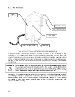
Page 26: ...quipped with an approved ASME safety valve The compressor owner is responsible for the proper sizing installation and maintenance and for periodic inspection and testing of the safety valve A pressure...

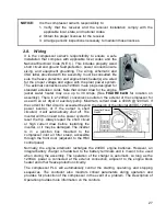
Page 27: ...e with an air dryer or auxiliary pump Maximum current draw is 400W 120VAC If the current for that circuit is exceeded beyond the design of the integral 24VDC 120VAC power inverter or if the output is...

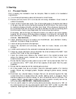
Page 28: ...cracks breaks and other damage g Confirm service valves for the automatic condensate drain valves are open h Check the engine lubrication oil level Maintain the oil level between the ADD mark and the...

Page 29: ...29 o Perform LED Test found in Terminal Options see Description of Operations manual for more information Confirm that all pilot lights operate and that the audible alarm sounds...

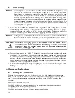
Page 30: ...were made WARNING Conductors supplying power to the starter panel are 24VDC Power connections and motor connections should only be made by qualified personnel with the supply power shut off properly d...

Page 31: ...held at user selected speed b Engine speed is reduced to 1200 RPM for 90 seconds If engine temperature is already below running temperature or if the engine is shutting off due to an alarm the cooldow...

Page 32: ...compressor The program number can be found on the KNW Title page accessible using the NAV menu and is shown on a label on the back of the HMI 5 1 Compressor Control Panel KNW Series air compressors c...

Page 33: ...objects A replaceable screen overlay is available to extend the service life of the touchscreen Use only a clean soft cloth and mild detergent to clean the screen If the HMI requires replacement disc...

Page 34: ...r is unloaded The intercooler drain line has a check valve to prevent backflow of drained condensate while the compressor is unloaded Inspect the check valve for proper operation This compressor is al...

Page 35: ...1 c Test Add cooling system supplemental additive d Change engine oil and engine oil filter e Change fuel system primary water filter element f Inspect cooling system hoses and clamps Replace as need...

Page 36: ...odic testing of the Safety Valve by a certified testing agency It is the responsibility of the compressor owner to have the valve properly tested at the mandated intervals l Test low oil pressure shut...

Page 37: ...and refill with a suitable replacement DO NOT MIX OILS WARNING Do not add or drain oil while the compressor is operating The compressor must be off and power disconnected before servicing can be perfo...

Page 38: ...NOT designed to support off road applications including Cat Engines DO NOT use API FA 4 oil for Cat engines Failure to meet the listed requirements will damage aftertreatment equipped engines and can...

Page 39: ...Element Water in the fuel can cause the engine to run rough Water in the fuel may cause an electronic unit injector to fail If the fuel has been contaminated with water the element should be changed...

Page 40: ...pipe and seal any drain holes in the muffler g Install pipe plug or cap on air outlet pipe h Remove the fuel from the secondary fuel filter housing Alternately empty and reinstall the spin on fuel fil...

Page 41: ...r to Special Instruction CAT Publication SEHS7633 Battery Test Procedure t Loosen all belts u Replace silica gel packs every 2 months v Rotate engine and compressor at least two rotations manually eve...

Page 42: ...tage Discharge Air 350 F Interstage Air 25 35 PSIG Pressure Loaded 2ND Stage Suction Air 105 F 13 15 Hg Vacuum Unloaded 2ND Stage Discharge Air 365 F Compressor Outlet Air 115 125 PSIG Load Unload Com...

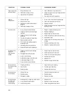
Page 43: ...leaking from bleed off silencer when loaded 1 Maximum 104 F 40 C 2 Clean coolers see section 6 4 3 Check for and remove any foreign material blocking air flow 4 Rebuild CCV High inlet air temperature...

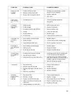
Page 44: ...acity Control Valve 4 Check transmitter connections and wiring 5 Press load button 6 Check output to unloading valve relay for voltage 7 Replace unloading valve relay 8 Rebuild or replace shuttle valv...

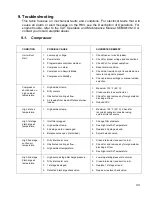
Page 45: ...drive shaft seal 1 Sump breather element plugged 2 Shaft seal worn 3 Worn bull gear bearings 1 Replace element 2 Replace shaft seal 3 Replace bull gear bearings Unit shuts down for no apparent reason...

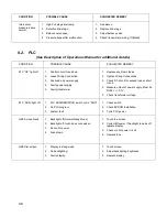
Page 46: ...ormer 1 Replace any blown fuses 2 Tighten Wiring Connections 3 Check DC circuit for excess load or short circuit 4 Measure output of power supply Must be DC24V 0 5V 5 Check transformer voltage PLC RUN...

Page 47: ...47...

Page 48: ...48 THIS PAGE LEFT BLANK...

Page 49: ...gers Machinery Co Inc 14650 SW 72nd Ave Portland Oregon 97224 7962 P O Box 230429 Portland Oregon 97281 0429 Phone 503 639 0808 Fax 503 639 0111 www rogers machinery com E Mail kobelco rogers machiner...

Reviews: