1.
1.0
GENERAL
1.1
Description
The Rogers KI-Series air compressors are designed to deliver compressed air at an average volume
equal to demand by loading and unloading within a pressure range. Maximum pressure capability is
generally limited by compressor drive motor horsepower.
The Rogers KIV Series air compressors are virtually identical to the KI Series except the primary control
flow control is accomplished by motor speed control through a VFD (Variable Frequency Drive). The
compressor and motor speed up and slow down within a range to adjust its output to match demands. At
demands lower than the minimum speed compressor output, pressure will rise, and the compressor will
unload.
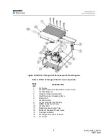
The basic compressor is a single-stage, positive displacement, lubricant injected twin screw unit. The
motor, compressor, associated equipment and components are mounted on a fabricated steel base within
a sound-attenuating enclosure. Air-cooled coolers dissipate heat of compression from the lubricant and
air using an independent cooling fan with motor. Controls and indicators pertaining to the compressor are
grouped on a common control panel. There are belt-driven units (10-50 HP) and direct-driven units (60-
100 HP) in the KI(V) Series.
Detailed discussion of the control systems is located in the Description of Operations / Display and
Controls manuals.
1.2
Principles of Compressor Operation
NOTE
The cycle of intake, compression, and discharge occurs five times during each 360-degree
rotation of the cambered rotor.
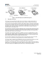
As shown in Figure 1, the compressor consists of two rotors within a casing. The male rotor (motor driven
rotor) is provided with five lobes and meshes with the female rotor which contains six grooves. Both rotors
are housed in a casing with two bores.
The casing is provided with an inlet port at the front (power input end of the compressor) and a discharge
port at the rear of the compressor opposite the compressor’s drive shaft. Both rotors are mounted on
single-row roller bearings at the inlet end and on tapered roller bearings at the discharge end. As the
rotors turn, air is drawn into the casing through the inlet port, trapping a fixed volume of air as the rotor
lobes move past the inlet port area.
This volume of air extends the entire length of the two rotors initially and is prevented from escaping by
the un-ported area of the cylinder rear wall. Oil is injected into the compression chamber during the
compression cycle as described in section 1.4.
As rotation continues, each lobe on the male rotor enters a groove in the female rotor, thus reducing the
volume of trapped air and resulting in continuous compression. Compression continues as the rotors
mesh together until the lobe and groove pair passes the discharge port.
At this point, the compressed air is released into the discharge line leading to the separator tank.
Note that the cycle of intake, compression, and discharge occurs five times during each 360 degree
rotation of the male rotor.
Summary of Contents for KI Series
Page 1: ...1 Model __________________ Serial __________________ Rotary Screw Air Compressors...
Page 8: ...7 INTENTIONALLY BLANK...
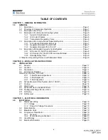
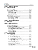
Page 9: ...8 CHAPTER 1 GENERAL INFORMATION...
Page 19: ...10 CHAPTER 2 INSTALLATION INSTRUCTIONS...
Page 26: ...17 CHAPTER 3 ELECTRICAL INFORMATION...
Page 30: ...21 CHAPTER 4 COMPRESSOR LUBRICANT...
Page 39: ...30 INTENTIONALLY BLANK...
Page 40: ...31 CHAPTER 5 AIR INLET FILTER INFORMATION...
Page 43: ...34 INTENTIONALLY BLANK...
Page 44: ...35 CHAPTER 6 COMPRESSOR OPERATIONS...
Page 49: ...40 INTENTIONALLY BLANK...
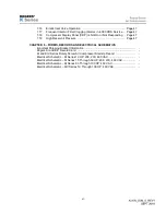
Page 50: ...41 CHAPTER 7 TROUBLESHOOTING...
Page 57: ...48 CHAPTER 8 FORMS RECORDS AND ELECTRICAL SCHEMATICS...
Page 58: ...49...
Page 59: ...50...
Page 60: ...51...
Page 61: ...52...
Page 62: ...53...
Page 63: ...54...
Page 64: ...55...
Page 65: ...56 INTENTIONALLY BLANK...
Page 66: ...57...

