19.
4. Main Motor Overloads - the main motor overload can be changed in the menu of the controller. It
will be necessary to power the machine back up to make these changes. Power up the machine,
but do not start it. See Description of Operations / Display and Control manual for overload
setting screen.
5. Fan Motor Overloads – the fan motor overload can be changed in the menu of the controller. It
will be necessary to power the machine back up to make these changes. Power up the machine,
but do not start it. See Description of Operations / Display and Control manual for overload
setting screen.
3.2
Motor Rotation
WARNING
Double check the wiring connections to make certain they are secure and properly made.
Incorrect connections could cause equipment damage, injury or death.
WARNING
It is critical that the rotation be established correctly during start up procedures and any
time that the motor leads or supply power phasing may have been changed.
An electronic phase monitor is supplied within the CDP controller. Connecting the machine to power
should indicate on the compressor CDP controller’s display whether the rotation is correct or needs to be
reversed, due to incoming supply power phasing.
The Display will read, ‘FAULT – TRIP: PHASES REVERSED’ when the rotation is incorrect.
Rotation must be checked for both the main motor and the fan motor before the machine is placed into
service. Rotation can be changed by switching any two of the three electrical supply leads with each other
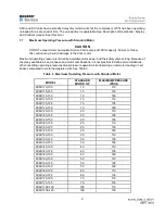
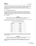
in the main connection terminal. See table 8 for correct rotation of various models.
3.3
Blowdown Valve
The sump blowdown valve (sometimes called control air solenoid) is a normally open solenoid valve that
is incorporated into the inlet valve control system and vents pressure from the separator tank back to the
compressor inlet downstream of the inlet filter. The purpose of this valve is to relieve separator tank
pressure when the machine is unloaded or turned off.
When unloaded, the blowdown valve relieves pressure in the separator tank to 30 - 40 psig. This reduces
power consumption by reducing the back pressure on the compressor while unloaded. The residual sump
pressure also provides the motive force to move the oil through the oil cooler, thermo mixing valve, oil
filter, and finally back into the compressor.
When the compressor is turned off, the compressor unloads and the STOP DELAY TIMER starts
counting down. When the STOP DELAY TIMER reaches zero the compressor motor stops. The RE-
START TIME DELAY now begins another count down to zero before the compressor can be restarted.
This allows sufficient time for the separator tank to blowdown to zero psig before attempting to re-start.
See Description of Operations / Display and Control manual for complete details.
3.4
Compressor Drive Motor
CAUTION
Incoming voltage must be within 10% of drive motor nameplate voltage, when the motor is
operating at full load. Operating the unit out of the 10% range will damage the drive motor
and associated components.
Summary of Contents for KI Series
Page 1: ...1 Model __________________ Serial __________________ Rotary Screw Air Compressors...
Page 8: ...7 INTENTIONALLY BLANK...
Page 9: ...8 CHAPTER 1 GENERAL INFORMATION...
Page 19: ...10 CHAPTER 2 INSTALLATION INSTRUCTIONS...
Page 26: ...17 CHAPTER 3 ELECTRICAL INFORMATION...
Page 30: ...21 CHAPTER 4 COMPRESSOR LUBRICANT...
Page 39: ...30 INTENTIONALLY BLANK...
Page 40: ...31 CHAPTER 5 AIR INLET FILTER INFORMATION...
Page 43: ...34 INTENTIONALLY BLANK...
Page 44: ...35 CHAPTER 6 COMPRESSOR OPERATIONS...
Page 49: ...40 INTENTIONALLY BLANK...
Page 50: ...41 CHAPTER 7 TROUBLESHOOTING...
Page 57: ...48 CHAPTER 8 FORMS RECORDS AND ELECTRICAL SCHEMATICS...
Page 58: ...49...
Page 59: ...50...
Page 60: ...51...
Page 61: ...52...
Page 62: ...53...
Page 63: ...54...
Page 64: ...55...
Page 65: ...56 INTENTIONALLY BLANK...
Page 66: ...57...

