46.
Discharge air temperature
excessive.
See “High Air Discharge Temperature”, Section 7.9.
Installation/Application.
Check other compressors on same system.
System requires compressed air
dryer.
Contact your Rogers factory representative.
Plant receiver needs draining.
Drain receiver. Contact your Rogers factory
representative. for automatic condensate drain
options.
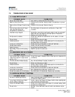
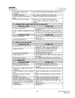
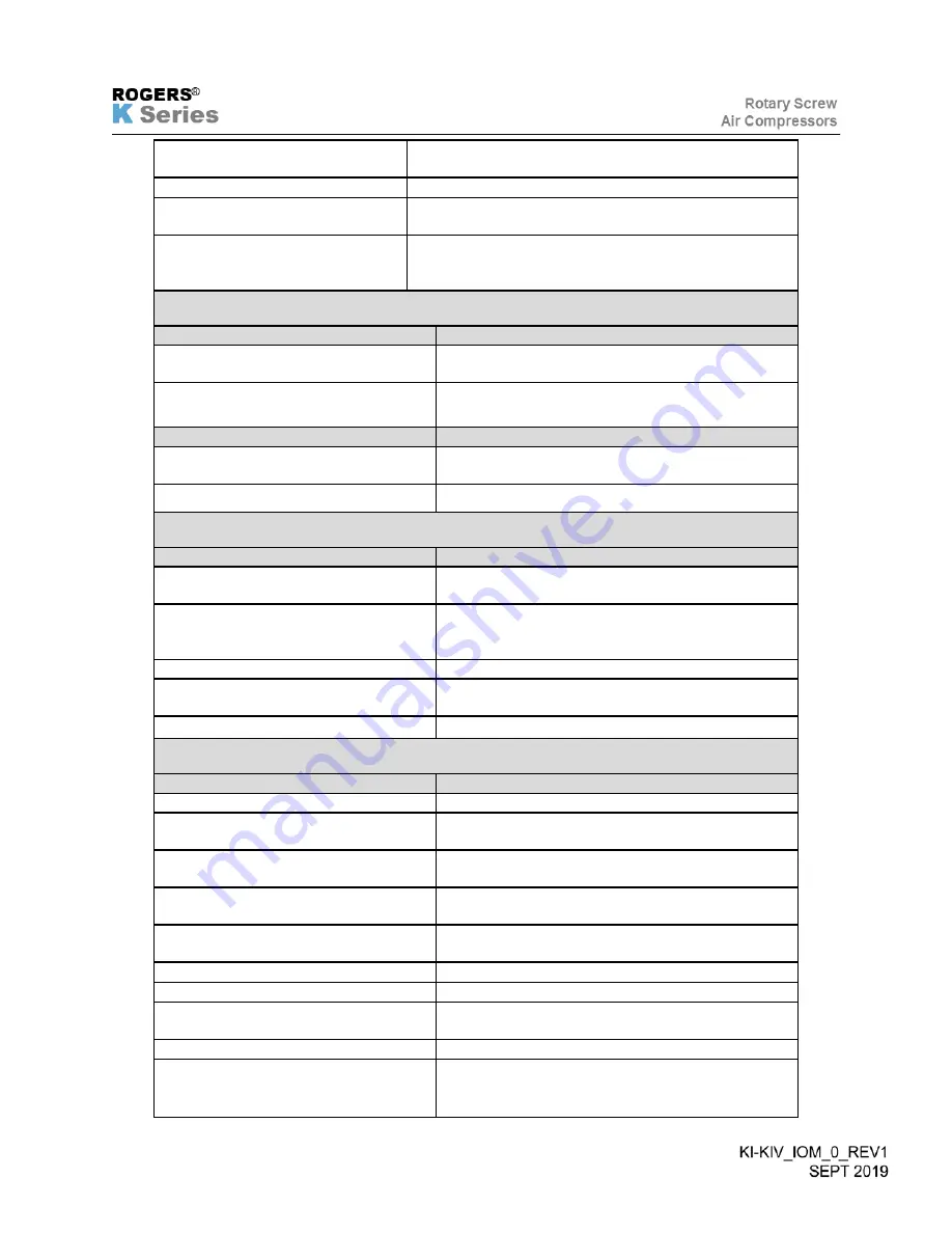
7.13 FREQUENT LUBRICANT FILTER CLOGGING
POSSIBLE CAUSE
CORRECTION
Incorrect lubricant filter.
Use genuine Rogers’ replacement filters rated for
this service.
Faulty, incorrect or inadequate inlet air
filter.
Replace air filter element. Check air inlet system
for leaks. Use genuine Rogers replacement filters.
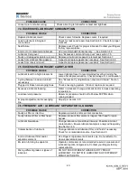
POSSIBLE CAUSE
CORRECTION
Lubricant breakdown.
See “Frequent Air/Lubricant Separator Clogging”,
Section 7.6.
Lubricant contamination.
See Section 4.0.
7.14 SAFETY VALVE OPENS
POSSIBLE CAUSE
CORRECTION
Unload pressure setting too high.
Reset unload pressure setting. See Description of
Operations / Display and Controls Manual.
Plugged separator.
Replace with new air/lubricant separator.
Determine cause of contamination. See
“Separator Clogging” Section 7.6.
Faulty pressure transmitter.
Test and replace if necessary.
Faulty safety valve.
Check safety valve for proper operation. Replace
as needed.
High reservoir pressure.
See “High Reservoir Pressure”, see Section 7.8.
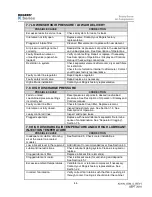
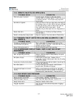
7.15 VIBRATION
POSSIBLE CAUSE
CORRECTION
Base not evenly supported.
Shim base as required. See Section 2.3.
Wooden pallet has rotted out.
Do not use wooden pallets for permanent
mounting.
Motor and/or compressor not evenly
supported.
Realign motor/compressor per Section 2.5 and 2.6
Loose compressor or motor mounting
bolts.
Realign motor/compressor per Section 2.5 and
2.6.
Improper compressor to motor
alignment
Realign motor/compressor per Section 2.5 and
2.6.
Defective motor bearing.
Contact your Rogers factory representative.
Defective compressor bearings.
Contact your Rogers factory representative.
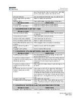
Machine excited from other equipment
operating nearby or discharge piping.
Machine must not vibrate while shut down. See
Section 2.11.
Piping strain.
See Section 2.11
Unbalanced fan.
Replace fan.
Summary of Contents for KI Series
Page 1: ...1 Model __________________ Serial __________________ Rotary Screw Air Compressors...
Page 8: ...7 INTENTIONALLY BLANK...
Page 9: ...8 CHAPTER 1 GENERAL INFORMATION...
Page 19: ...10 CHAPTER 2 INSTALLATION INSTRUCTIONS...
Page 26: ...17 CHAPTER 3 ELECTRICAL INFORMATION...
Page 30: ...21 CHAPTER 4 COMPRESSOR LUBRICANT...
Page 39: ...30 INTENTIONALLY BLANK...
Page 40: ...31 CHAPTER 5 AIR INLET FILTER INFORMATION...
Page 43: ...34 INTENTIONALLY BLANK...
Page 44: ...35 CHAPTER 6 COMPRESSOR OPERATIONS...
Page 49: ...40 INTENTIONALLY BLANK...
Page 50: ...41 CHAPTER 7 TROUBLESHOOTING...
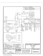
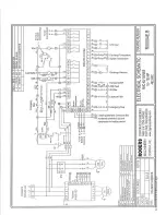
Page 57: ...48 CHAPTER 8 FORMS RECORDS AND ELECTRICAL SCHEMATICS...
Page 58: ...49...
Page 59: ...50...
Page 60: ...51...
Page 61: ...52...
Page 62: ...53...
Page 63: ...54...
Page 64: ...55...
Page 65: ...56 INTENTIONALLY BLANK...
Page 66: ...57...

