SMIQ
Digital Standard IS-95 CDMA
1125.5555.03
E-9
2.143
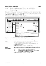
(CLOCK...)
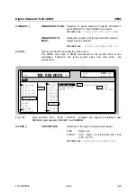
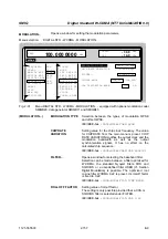
CLOCK SOURCE
Selection of clock source.
INT
SMIQ uses internally generated clock
signals.
EXT
An external chip clock is fed in at connec-
tor SYMBOL CLOCK. Multifolds of the
chip clock are fed in at connector BIT
CLOCK .
The clock synthesizer on the modulation
coder is synchronized to this clock.
Parameter CHIP RATE has to be set with
an accuracy of
±
1 %.
The polarity, the trigger threshold and the
input resistance of the SYMBOL CLOCK
input can be modified in menu DIGITAL
MOD - EXT INPUTS.
IEC/IEEE-bus
:SOUR:IS95:CLOC:SOUR INT
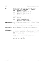
DELAY
Setting the delay of generated modulation signal to
an external clock.
This can be used, for example, for synchronization
with a second unit to achieve time synchroneity
between the modulation signals of the two units.
The displayed setting resolution of 1/100 symbol is
only attained for symbol-clock frequencies below
100 kHz.
The resolution is reduced with increasing frequency.
At a chip rate of 1.2288 Mcps, the resolution equals
the chip duration
×
0.1.
IEC/IEEE-bus
:SOUR:IS95:CLOC:DEL 0.5
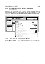
TOTAL POWER
Display of the total power of all active code channels. The TOTAL POWER is
calculated when the modulation is active (STATE = ON). It is the sum of the
channel power of all active channels. If the value is not equal 0 dB then all active
channel power were internally adjusted so that the total power equals 0 dB (the
power relation between single code channels is not affected!) This is nessessary
to keep the setted output power (LEVEL) constant. In addition to this average
power (LEVEL) the peak envelope power (PEP) is also indicated in the header of
the display. The value for PEP is calculated based on a worst case. The actual
peak powers are mostly smaller.
IEC/IEEE-bus command
:SOUR:IS95:POW?
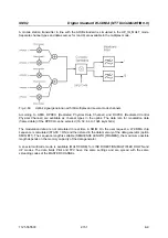
ADJUST
TOTAL POWER
Changes the power of every code channel switched on. After this adjustment
the total power is 0 dB. The power relation between single active code
channels is not affected.
IEC/IEEE-bus command
:SOUR:IS95:POW:ADJ

