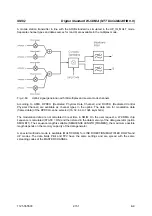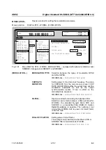
Digital Standard W-CDMA (NTT DoCoMo/ARIB 0.0)
SMIQ
1125.5555.03
E-9
2.160
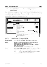
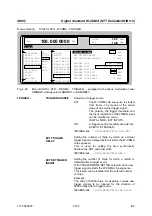
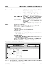
(TRIGGER...)
TRIGGER OUT 1/2
Selection of signals for outputs TRIGOUT 1 and
TRIGOUT 2 of connector PARDATA.
The time specifications are valid only if the frequency
of the internal clock generation is not modified with
the parameter CHIP RATE VARIATION.
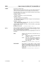
SLOT
0.625 ms time slot clock
IEC/IEEE-bus
:
:SOUR:WCDM:TRIG:OUTP1 SLOT
RADIO FRAME
10 ms frame clock
IEC/IEEE-bus
:
:SOUR:WCDM:TRIG:OUTP1 RFR
CHIP SEQUENCE Marker signal for identifying the
PERIOD
periodic repetition of the gene-
rated chip sequence
IEC/IEEE-bus
:
:SOUR:WCDM:TRIG:OUTP1 CSP
TRIGGER OUT 1/2 POL
Selection of signal polarity at outputs TRIGOUT 1
and TRIGOUT 2 of the PARDATA connector.
IEC/IEEE-bus
:SOUR:WCDM:OUTP2:POL POS
TRIGGER OUT 1/2
DELAY
Setting the number of chips by which the selected
trigger signal is delayed.
IEC/IEEE-bus
:SOUR:WCDM:OUTP2:DEL 0
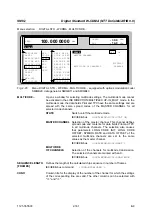
CLOCK...
Enables the selection of the clock source of the chip clock.
INT
SMIQ uses internally generated clock signals.
EXT
A chip clock should externally be applied to connector SYMBOL
CLOCK. Parameter CHIP RATE should be correctly set with a
precision of
±
1 %.
The polarity, the trigger threshold and the input resistance of the
SYMBOL CLOCK input can be modified in menu
DIGITAL MOD - EXT INPUTS.
IEC/IEEE-bus
:SOUR:WCDM:CLOC:SOUR INT
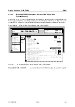
TOTAL POWER
Display of the total power of all active code channels. The TOTAL POWER is
calculated when the modulation is active (STATE = ON). It is the sum of the
channel power of all active channels. If the value is not equal 0 dB then all active
channel power were internally adjusted so that the total power equals 0 dB (the
power relation between single code channels is not affected!) This is nessessary
to keep the setted output power (LEVEL) constant. In addition to this average
power (LEVEL) the peak envelope power (PEP) is also indicated in the header of
the display. The value for PEP is calculated based on a worst case. The actual
peak powers are mostly smaller.
IEC/IEEE-bus command
:SOUR:WCDM:POW?
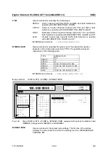
ADJUST
TOTAL POWER
Changes the power values of all activated code channels. After this
adjustment the total power is 0 dB. The power relation between single active
code channels is not affected.
IEC/IEEE-bus command
:SOUR:WCDM:POW:ADJ

