Manual Operation
R&S
®
SMU200A
84
Quick Start Guide 1007.9822.62 ─ 13
●
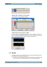
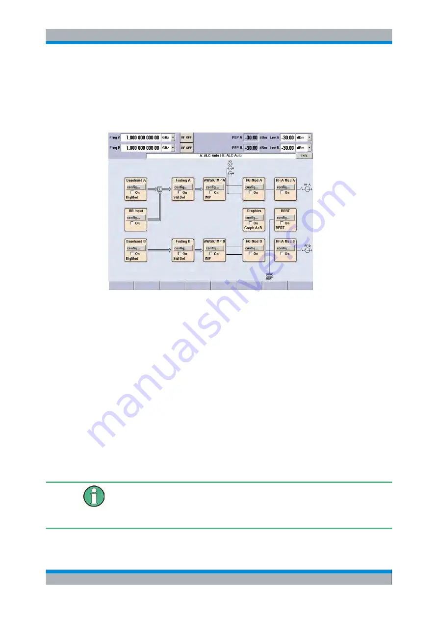
The block diagram shows the instrument configuration, the signal characteristic as
well as the inputs and outputs used and permits interactive operation via graphics
elements. Active menus and graphs are displayed on top of the block diagram.
●
Winbar with labelled softkeys for menu display.
The block diagram in the figure below shows a fully equipped instrument.
Fig. 4-1: Block diagram of a fully equipped two-path R&S Signal Generator
4.2.1 Settings Displayed in the Header Section
Frequency/level settings and a few status messages (see
, on page 85) are displayed in the header field of the screen.
The display may vary depending on the instrument's operating mode:
●
In the case of two-path instruments, the RF information for the two paths is displayed
in two lines.
●
In the sweep mode, the current frequency or level of the output signal is displayed.
The status message "SweepMode" is displayed in the info line.
●
In the list mode, neither the current frequency nor level is displayed, the indication is
dimmed.
●
If user correction is active, the status message "UCorr" is displayed in the info line.
●
In the case of digital modulation, "Freq" indicates the frequency, "PEP" the peak
envelope power and "Level" the average level.
The value displayed in the "Freq" and "Level" field does not consider any offset set or
multiplier factor.
For more information see "RF Frequency and Phase" and "RF Level" in the Operating
Manual.
Display
Summary of Contents for 1141.2005.02
Page 27: ......
Page 74: ...Preparing for Use R S SMU200A 57 Quick Start Guide 1007 9822 62 13 LXI Configuration ...
Page 75: ......
Page 95: ......
Page 135: ......
Page 141: ......
Page 144: ...Index R S SMU200A 127 Quick Start Guide 1007 9822 62 13 Winbar 89 Windows XP 33 access 34 ...

