Hardware Interfaces
R&S
®
SMU200A
122
Quick Start Guide 1007.9822.62 ─ 13
Pin
Signal
Description
47
BITCLK
Output Bit clock for internal mode.
For two-path instruments, the signal for Path B can be applied to one of the
USER interfaces.
48
USER 2
USER input/output which can be configured for various purposes.
49
SYMBCLK
Symbol clock output for internal mode.
With two-path instruments, the signal for Path B can be applied to one of the
USER interfaces.
50
not used
not used
A.3 Monitor Connector (MONITOR)
The 15-pin Sub-D female connector MONITOR at the rear panel is intended for connect-
ing an external VGA monitor.
Table 1-3: Pin assignment of the MONITOR connector
Monitor Connector
Pin
Signal
Pin
Signal
Pin
Signal
1
Red (output)
6
GND
11
(NC)
2
Green (output)
7
GND
12
(NC)
3
Blue (output)
8
GND
13
HSYNC (output)
4
(NC)
9
GND
14
VSYNC (output)
5
GND
10
GND
15
(NC)
A.4 BERT Connector
The 9-pin Sub-D connector BERT at the rear panel is available for the input signals of
the integrated bit error rate tester (option BER/BLE Measurement (R&S SMU-K80)).
Table 1-4: Pin assignment of the BERT connector
Monitor Connector
Pin
Signal
Pin
Signal
1
GND
6
CLOCK
2
GND
7
DATA
3
GND
8
DATA ENABLE
4
GND
9
RESTART
5
GND
The input signals are not terminated in the instrument. The impedance (50 ohm) and the
threshold (0.0128..1.998 V) of the inputs can be set in the "BERT" menu.
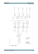
The following figure shows the circuit diagram of the BERT function.
Monitor Connector (MONITOR)
Summary of Contents for 1141.2005.02
Page 27: ......
Page 74: ...Preparing for Use R S SMU200A 57 Quick Start Guide 1007 9822 62 13 LXI Configuration ...
Page 75: ......
Page 95: ......
Page 135: ......
Page 141: ......
Page 144: ...Index R S SMU200A 127 Quick Start Guide 1007 9822 62 13 Winbar 89 Windows XP 33 access 34 ...


