Preparing for Use
R&S
®
SMU200A
20
Quick Start Guide 1007.9822.62 ─ 13
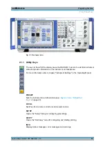
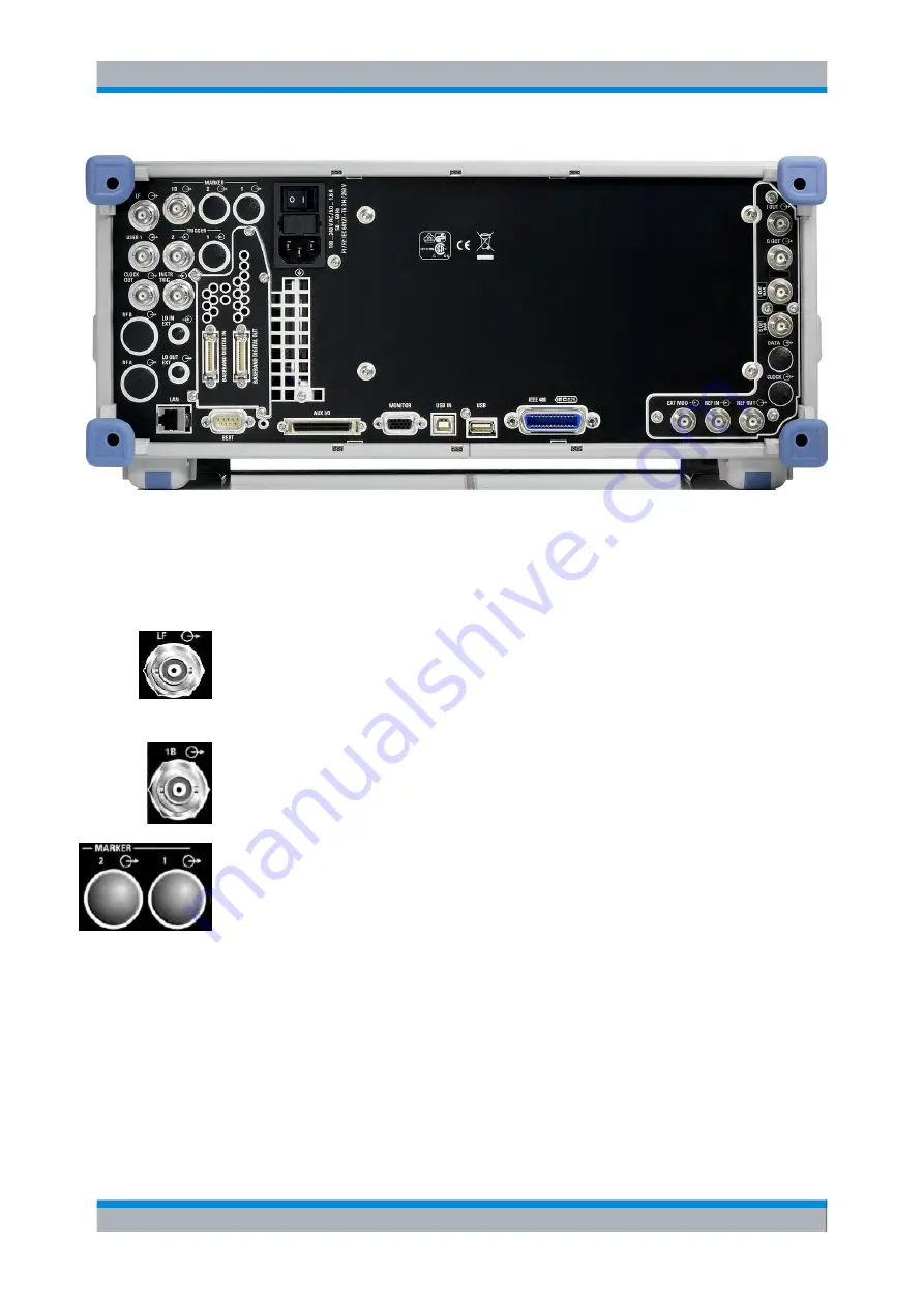
Fig. 2-2: Rear panel view
2.2.1 Description of the Connectors
LF
(path A only)
Output for internal LF modulation generator signal.
See also data sheet and Operating Manual, section "LF Generator and LF Output".
MARKER 1B
Output for user-programmable marker signal 1 of path B for triggering and control of
external devices. Marker outputs are permanently assigned (see
MARKER 1/ MARKER 2
Rear Panel Connectors for path A (option R&S SMU-B81) and path B (option R&S SMU-
B82).
These options are recommended for use of the instrument in a 19" rack. Installing the
instrument in a 19" rack requires a rack adapter or an adapter for telescopic sliders (refer
to data sheet for order number).
Marker outputs are permanently assigned (see
See also
chapter 2.3.2, "Placing or Mounting the Instrument"
Rear Panel Tour
Summary of Contents for 1141.2005.02
Page 27: ......
Page 74: ...Preparing for Use R S SMU200A 57 Quick Start Guide 1007 9822 62 13 LXI Configuration ...
Page 75: ......
Page 95: ......
Page 135: ......
Page 141: ......
Page 144: ...Index R S SMU200A 127 Quick Start Guide 1007 9822 62 13 Winbar 89 Windows XP 33 access 34 ...

