49
Instrument Functions
49
Instrument Functions
the interlinked channels are switched off; however, the
MASTER ON/OFF key remains active. At any given time,
the outputs can be reactivated via corresponding channel
option key. In case of any excess current, it will immedi-
ately be switched off again.
5.2.2 Fuse Delay
The DELAY function allows you to select a fuse delay by
10ms to 10s. This is intended to ignore the current peaks
that occur, depending on the load, when the instrument is
switched on so the fuse is not triggered (e.g. in case of a
capacitive load). This refers exclusively to a fuse trigger de-
lay at the measured channel, not a trigger delay between
individual channels. The fuse delay can be changed via
knob or numeric keypad. Select the delay for each channel
individually by using the respective soft menu key. With
the soft menu key CHANNEL the respective channel can
be selected.
5.3 Over Voltage Protection (OVP)
The OVP is individually adjustable for each channel (soft
menu key CHANNEL). The over voltage protection is
preset at the factory to 32.050 V; however, this may be re-
duced with the soft menu key LEVEL to match the require-
ments of the respective application.
You can choose from two different OVP options:
❙
Measured
(MEAS): In the MEAS mode, OVP will switch
off if the measured value exceeds the set limit.
❙
Protected
(PROT): In the PROT mode, the instrument
output will not be switched off in case the set limit is
exceeded. In addition, the measured value will be
monitored (see MEASURED operating mode).
With the soft menu key ACTIVATE the OVP of the respec-
tive channel will be activated (ON) or disabled (OFF). If
the voltage exceeds the preset value U
MAX
, the respec-
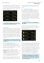
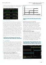
Fig. 5.4: Fuse Linking example
Fig. 5.2 shows that exceeding the current limit at CH1 leads to
automatically having CH2 and CH3 switched off.
The fuse delay function is only available when the channel is acti-
vated (MASTER ON). This function is not activated in the regular
function mode.
tive channel will be switched off to protect the load. If the
over voltage protection is tripped, OVP will flash in the
display.
5.4 Overload Protection (OPP)
The overload protection is individually adjustable for each
channel (soft menu key CHANNEL). Depending on the
instrument type the overload protection is preset at the
factory to the maximum power value P
MAX
(per channel);
however, this may be reduced to match the requirements
of the respective application. With the soft menu key ACTI-
VATE the OPP of the respective channel will be activated
(ON) or disabled (OFF). If the power exceeds the preset
value Pmax, the respective channel will be switched off to
protect the load. If the overload protection is tripped, OPP
will flash in the display.
5.5 Tracking Function
The tracking function allows you to interlink multiple
channels. It is possible to change both the voltage and the
current limit up to the maximum value for the individual
channels simultaneously.
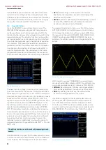
To access the tracking mode, press the TRACK key. After
activating the TRACK function (TRACK LED is illuminated)
you can select the individual channels via CH1, CH2 and
CH3 key. If e.g. the soft menu key U is activated, you can
change the voltage of one of these channels via knob or
arrow keys, the voltages of the interlinked channels will be
changed by the identical amount. The same applies to the
current and the usage of the soft menu key I. During
tracking, the R&S®HMC804x power supply retains the
previously selected voltage and current difference
between the channels until a channel has reached the
minimum or maximum value of the voltage or current.
The TRACK function is only available with R&S®HMC8042 and
R&S®HMC8043.
Fig. 5.5: TRACK function
The TRACK function can only be used in the local operating mode
(frontal operation). The TRACK function may not be used via
remote operating mode (SCPI commands) since according to the
SCPI standards, each channel is considered an "instrument" and
has to be activated separately.
www.allice.de
Allice Messtechnik GmbH
Summary of Contents for 3593.1006.02
Page 2: ...www allice de Allice Messtechnik GmbH ...
Page 3: ...71 Appendix 71 Appendix www allice de Allice Messtechnik GmbH ...
Page 37: ...35 Anhang 35 Anhang www allice de Allice Messtechnik GmbH ...
Page 39: ...www allice de Allice Messtechnik GmbH ...
Page 40: ...71 Appendix 71 Appendix www allice de Allice Messtechnik GmbH ...
Page 73: ...68 Appendix 68 Appendix www allice de Allice Messtechnik GmbH ...
Page 74: ...69 Appendix 69 Appendix www allice de Allice Messtechnik GmbH ...
Page 75: ...70 Appendix 70 Appendix www allice de Allice Messtechnik GmbH ...


