52
Advanced Operating Functions
52
Advanced Operating Functions
6.2 Analog In
On the back panel of the instrument, you can find the con-
nectors for analog control signals (please refer to chapter
6.1 terminal connector). The R&S®HMC804x enables you
to optionally control the output voltages of the power sup-
ply by means of a voltage signal (0 V to 10 V) or current si-
gnal (4 mA to 20 mA). Do not connect both sig-nals simul-
taneously because there is no galvanic isolation between
voltage input and current loop. You must exclusively use
one mode or the other. The Analog In menu will be opened
via soft menu key ANALOG IN. With the soft menu key
CHANNEL the respective channel will be chosen, the soft
menu key ACT.CH activates the Analog In function for
the selected channel. Additionally, the Analog In function
can be activated or disabled via the channel short menu
(ANALOG IN ON/OFF). Use the soft menu key MODE to
differentiate between two different setting modes:
❙
LIN:
Use the LIN mode to proportionally control the voltage
that is set at the front panel of the instrument.
❙
STEP:
If the threshold is exceeded, the STEP setting issues the
voltage of the selected output that is set at the front
panel of the instrument. Otherwise 0 V will be issued.
The threshold for the STEP mode can be adjusted via soft
menu key THRESHOLD. Use the soft menu key INPUT to
differentiate between voltage (U) or current signal (I). You
can use any combination and configuration for the outputs
on which the interface is intended to operate.
6.2.1 Analog In - Example
Fig. 6.4 shows an Analog In example in the operating
mode LIN which proportionally controls the voltage set at
the front panel of the instrument. An external power
supply unit is used as the source. The connection is
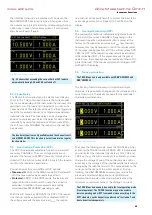
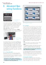
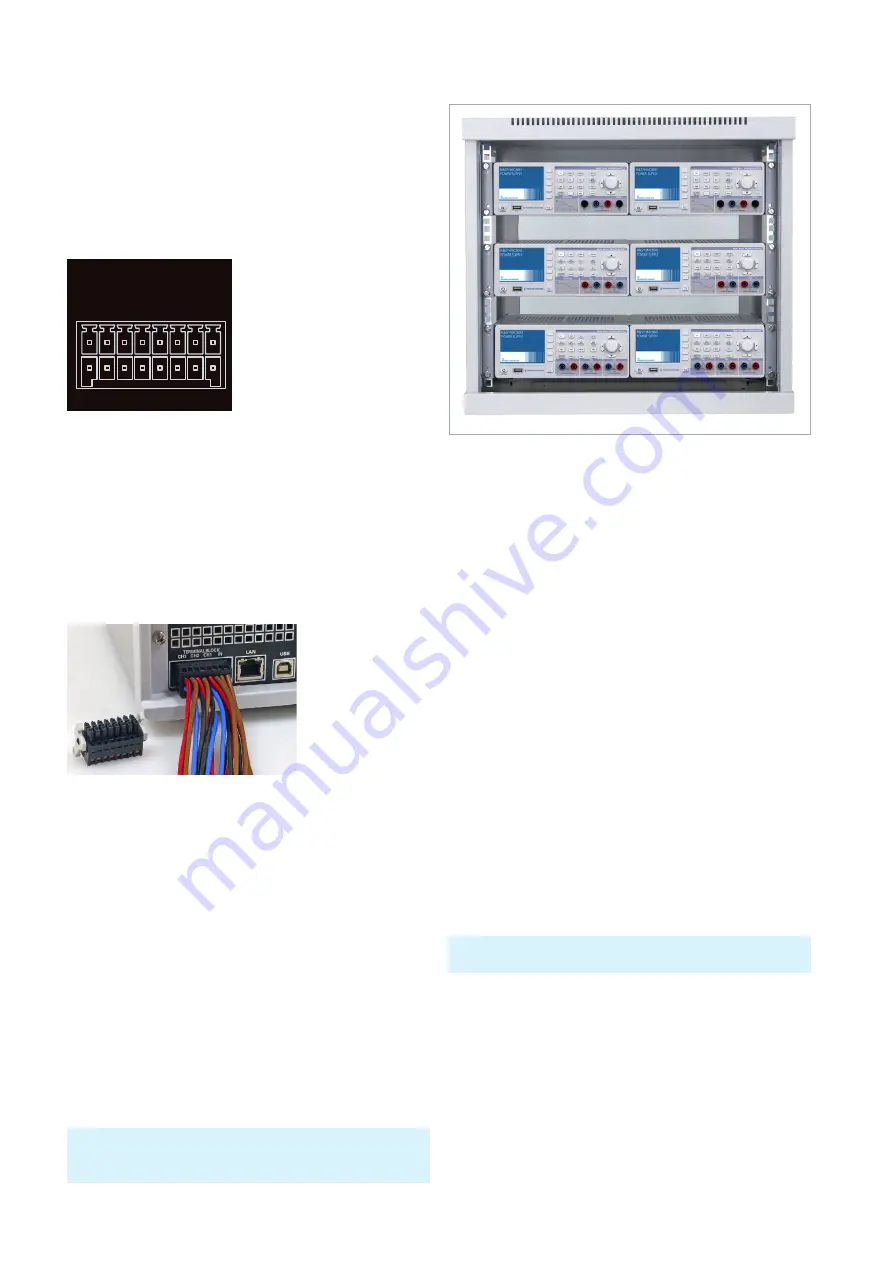
Fig. 6.3: Example for 19“ rack mount
The Analog In function can not be used with sequencing, Easy-
Ramp or arbitrary function simultaneously.
6 Advanced Ope-
rating Functions
6.1
Terminal Connector
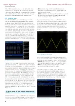
The terminal connector on the back panel of the instru-
ment allows you to execute the voltages / currents of all
channels (including SENSE). The 16-pole terminal block
includes the following connectors for each channel:
❙
P+
(corresponds to + socket on the front panel)
❙
P-
(corresponds to - socket on the front panel)
❙
S+
and
S-
(SENSE connectors)
❙
U+
,
U-
,
I+
,
I-
(voltage/current interface) +
Trigger
To connect lines, you can use e.g. a plug-in terminal block
connector. This allows for the easy integration into 19``
rack systems (please refer to fig. 6.2). The SENSE lines
(only available on the back panel for the R&S®HMC8042
and R&S®HMC8043) allow you to compensate voltage
drops on the supply lines to the load so that the actual
selected voltage is applied to the load. The instrument au-
tomatically detects when the SENSE lines are connected
and it regulates the output voltage directly at the load. If
the SENSE lines are connected via S+ and S-, the display
shows SENSE. The maximum compensation value of the
lead resistances is 1V.
6.1.1 19“ Rack Mount Kit
To install a 19“ rack, you can use the rack mount set
R&S®HZC95. When one or more R&S®HMC804x instru-
ments are installed in a 19“ rack, it is important to ensure
that sufficient space is available for adequate cooling (see
example for rack mount fig. 6.3).
Fig. 6.1: Terminal block with
connector assignment
USB
HMC 8043 POWER SUPPLY
100-240 V ±10% / 50-60 Hz
200 WATT (max.)
FUSE: T3,15L250V
IEEE-488
SERIENNUMMER
TERMINALBLOCK
CH
3
CH
2
CH
1
IN
TERMINALBLOCK
CH3 CH2 CH1 IN
P+ S+ P+ S+ P+ S+ U+ I+
P- S- P- S- P- S- U- I-
Engineered in Germany
Manufactured in Czech Republic
F-5013569 MC 253564
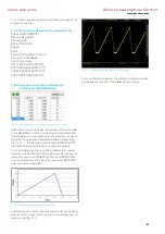
Fig. 6.2: Example
plug-in terminal block
connector
The installation in 19“ racks requires a minimum distance of
1 RU between the rack frames. When using 1 RU blank covers, it
is recommended to choose perforated blank covers.
www.allice.de
Allice Messtechnik GmbH
Summary of Contents for 3593.1006.02
Page 2: ...www allice de Allice Messtechnik GmbH ...
Page 3: ...71 Appendix 71 Appendix www allice de Allice Messtechnik GmbH ...
Page 37: ...35 Anhang 35 Anhang www allice de Allice Messtechnik GmbH ...
Page 39: ...www allice de Allice Messtechnik GmbH ...
Page 40: ...71 Appendix 71 Appendix www allice de Allice Messtechnik GmbH ...
Page 73: ...68 Appendix 68 Appendix www allice de Allice Messtechnik GmbH ...
Page 74: ...69 Appendix 69 Appendix www allice de Allice Messtechnik GmbH ...
Page 75: ...70 Appendix 70 Appendix www allice de Allice Messtechnik GmbH ...


