66
Appendix
66
12 Appendix
12.1 List of Figures
Fig. 1.2: Back panel R&S®HMC804x with connectors
Fig. 1.3: Connectors on the front panel of the instrument 40
Fig. 1.4: Product labeling in accordance with EN 50419 41
Fig. 2.1: Front panel of the ¸HMC8043
Fig. 2.2: Back panel of ¸HMC8043
Fig. 4.1 Display values R&S®HMC8041
Fig. 4.2: Numeric keypad with function keys
Fig. 4.3 Value display R&S®HMC8043
Fig. 4.4: R&S®HMC8043 power hyperbola
Fig. 5.2: Display values CV/CC R&S®HMC8042
Fig. 5.4: Fuse Linking example
Fig. 5.7: Arbitrary waveform example
Fig. 5.8: EasyArb Editor page 2|2
Fig. 5.9: Arbitrary-editor example (excerpt) HMExplorer
Fig. 5.10: Arbitrary example HMExplorer software
Fig. 5.11: Output arbitrary example on an oscilloscope
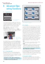
Fig. 6.1: Terminal block with connector assignment
Fig. 6.2: Example plug-in terminal block connector
Fig. 6.3: Example for 19“ rack mount
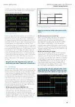
Fig. 6.5: Example for Sequencing
Fig. 6.6: Delay between CH1 and CH2
Fig. 6.8: Example for serial mode
Fig. 6.9: Example for parallel mode
Fig. 6.10: Power supply quadrants diagram
Fig. 6.11: R&S®HMC8043 connection
Fig. 6.12: Statistic menu R&S®HMC8043
Fig. 6.13: Statistic example R&S®HMC8042
Fig. 9.1: Firmware update menu
Fig. 9.4: Enter the device name
Fig. 10.5: NI-VISA installation instructions
Fig. 10.6: NI-VISA feature installation locally
Fig. 10.10: Instrument driver installation
2
Specifications
Trigger Input
Trigger response time
<1 ms
Min. trigger interval
10 ms
Trigger level
TTL
Edge direction
rising, falling
Arbitrary (EasyARB)
Parameter
Voltage, current, time, interpolation
mode (y/n)
Number of Points
max. 512
Dwell time
10 ms to 600 s
Repetition rate
continous or burst mode with 1 to 255
repetitions
Trigger
manually, interface, trigger input
Logging
Sampling rate
1000 Sa/s,100 Sa/s,10 Sa/s,
1 to 3600 Sa/s
Resolution
¸HMC8043
1 mV / 0.1 mA (<100 Sa/s)
10 mV / 1 mA (1000 Sa/s)
¸HMC8042 /
¸HMC8041
1 mV / 1 mA (<100 Sa/s);
10 mV / 10 mA (1000 Sa/s)
Memory
Internal or external memory
(USB memory sticks)
Maximum number of points
limited by memory
Output Sequencing
Synchronicity
<100 µs
Delay per channel
1 ms to 60 s
Remote Interfaces
Connectors
USB-TMC, USB-CDC (Virtual COM), LAN
(LXI), GPIB (optional)
Miscellaneous
Input power option
100 VAC to 240 VAC (±10 %) 50/60 Hz
Maximum input power
200 W
Fuse
T3, 15L 250 V
Operating temperature
0 °C to +40 °C
Storage temperature
-20 °C to +70 °C
Humidity
5 % to 80 %
Display
3.5” / QVGA
Dimensions (H x W x D)
88 x 222 x 280 mm
Rack mount capability
(half 19“)
Yes
Weight
2.6 kg
Accessories included:
Line cord, operating manual
Recommended accessories:
¸HZC95
19” rackmount kit, 2HE
¸HZ10S
5 x silicon test lead (black)
¸HZ10R
5 x silicon test lead (red)
¸HZ10B
5 x silicon test lead (blue)
¸HZ72
IEEE-488 (GPIB) interface cable, 2 m
The specifications are based on a 30 min warm-up period.
www.allice.de
Allice Messtechnik GmbH
Summary of Contents for 3593.1006.02
Page 2: ...www allice de Allice Messtechnik GmbH ...
Page 3: ...71 Appendix 71 Appendix www allice de Allice Messtechnik GmbH ...
Page 37: ...35 Anhang 35 Anhang www allice de Allice Messtechnik GmbH ...
Page 39: ...www allice de Allice Messtechnik GmbH ...
Page 40: ...71 Appendix 71 Appendix www allice de Allice Messtechnik GmbH ...
Page 73: ...68 Appendix 68 Appendix www allice de Allice Messtechnik GmbH ...
Page 74: ...69 Appendix 69 Appendix www allice de Allice Messtechnik GmbH ...
Page 75: ...70 Appendix 70 Appendix www allice de Allice Messtechnik GmbH ...


