44
Brief Description
44
Brief Description
3 Brief Description
The following chapter introduces the most important
R&S®HMC804x functions and features.
3.1
Operating the Instrument
Prior to operating the instrument for the first time, please
be sure to observe the safety instructions mentioned pre-
viously!
After connecting power cord und switching on the power
switch on the instrument back panel the R&S®HMC804x
can be switched on via POWER ON key on the instru-
ment front panel. When switching the instrument on, the
R&S®HMC804x power supply will use the same opera-
ting mode that was in use at the time the unit was last
switched off. All instrument settings (nominal values)
are stored in a nonvolatile memory and will be retrieved
when switching the instrument on again. By default, the
output signals (MASTER ON/OFF key) are switched off at
the beginning of operations. This is intended to prevent a
connected load from being serviced unintentionally when
switching the instrument on. The intent is also to avoid de-
struction caused by an exceedingly high voltage or power
(due to previously stored instrument settings).
3.2 Selecting the Parameters
Each function and operating mode of the power supply
can be selected with the keys on the front panel of the
instrument. Use the respective function or channel keys to
select basic functions such as voltage, current or Arbitrary
settings. Advanced functions are managed by use of soft
menu keys to the right of the display. Pressing the SHIFT
key activates the numeric keypad.
3.3 Selecting the Channels
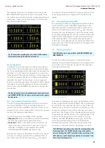
To select a channel, press the corresponding channel
option key CH1, CH2 or CH3. If you press a channel op-
tion key, the channel LEDs are illuminated. Subsequent
settings refer to the selected channels. You should always
first select the required output voltage and the maximum
required power before activating the channels by press-
ing the CH1 ON/OFF, CH2 ON/OFF or CH3 ON/OFF key.
Press the MASTER ON/OFF key to activate the previously
selected channels. If the MASTER ON/OFF has been acti-
vated, the LED is illuminated.
3.4 Selecting the Output Voltage
To select the output voltage, press the corresponding
channel option key (CH1, CH2 or CH3) and the soft menu
key VOLTAGE. If the corresponding channel has been
activated, the LED is illuminated. If the soft menu key
VOLTAGE or CURRENT have been activated, the LEDs for
the arrow keys and the SHIFT key will also be illuminated.
The nominal value for the output voltage can be selected
via know and the numeric keypad. If you wish to select
the channel voltage via knob, the VOLTAGE key must
be activated so you can select the desired decimal point
via arrow keys. The nominal value of the output voltage
is increased by turning the knob to the right, and it is
decreased by turning it to the left. The same applies to the
value selection of the current.
Depending on the instrument type, up to 3 galvanically
isolated and hence combinable channels are available. The
R&S®HMC8043 has three identical channels with a con-
tinuous voltage range of 0 V to 32 V. All instrument types
(R&S®HMC8041, R&S®HMC8042, R&S®HMC8043) provide
a total operating performance of max. 100 W.
All power supplies feature galvanically isolated, floating
overload and short-circuit proof outputs and may be
connected in series or in parallel, thus making higher cur-
rents and voltages available.
3.5 Tracking-Function
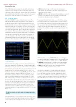
The tracking function allows you to interlink multiple chan-
nels. It is possible to change both the voltage and the cur-
rent limit for the individual channels simultaneously.
To access the Tracking Mode, press the TRACK key. Then
you can select the individual channels. If you change
the voltage value by using the soft menu key U and the
knob, the voltage values of the interlinked channels will be
changed by the identical amount. The same applies to the
current in relation to the soft menu key I. During tracking,
the R&S®HMC804x power supply retains the previously
selected voltage and current difference between the chan-
nels until a channel has reached the minimum or maxi-
mum value of the voltage or current. If the TRACK key has
been activated, the LED is illuminated in white. This key
remains activated until it is pressed again.
3.6 Fuse Setting
To protect a connected, sensitive load even better, the
R&S®HMC804x power supply includes an electronic fuse.
The ADV menu and the soft menu key FUSE allow the se-
lection or deletion of fuses. If the electronic fuse has been
activated for one or more channels, FUSE will be shown in
the display for each selected channel.
The LINK (Fuse Linking) function allows you to logically
interlink channels with their electronic fuses. If the current
for a channel exceeds the value Imax and if the electronic
fuse for this channel has been activated, all channels inter-
linked with this channel will be switched off. In addition,
you can use the soft menu key DELAY to set a fuse delay.
For instance, this prevents the fuse to be triggered in case
of a capacitive load when switching the instrument on.
3.7 EasyArb Editor
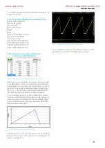
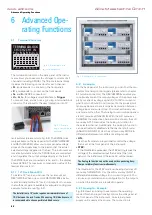
The R&S®HMC804x allows you to generate freely pro-
grammable waveforms which can be reproduced within
the limits set by the instrument for voltage and current
for the respective channel. The arbitrary function can be
configured and executed via control panel or external
interface.
www.allice.de
Allice Messtechnik GmbH
Summary of Contents for 3593.1006.02
Page 2: ...www allice de Allice Messtechnik GmbH ...
Page 3: ...71 Appendix 71 Appendix www allice de Allice Messtechnik GmbH ...
Page 37: ...35 Anhang 35 Anhang www allice de Allice Messtechnik GmbH ...
Page 39: ...www allice de Allice Messtechnik GmbH ...
Page 40: ...71 Appendix 71 Appendix www allice de Allice Messtechnik GmbH ...
Page 73: ...68 Appendix 68 Appendix www allice de Allice Messtechnik GmbH ...
Page 74: ...69 Appendix 69 Appendix www allice de Allice Messtechnik GmbH ...
Page 75: ...70 Appendix 70 Appendix www allice de Allice Messtechnik GmbH ...


