background image

Putting into Operation

R&S

®

NGA100

12

Getting Started 5601.8902.02 ─ 03

The instrument is designed for use in the following sectors: Industrial, residential,
business and commercial areas and small businesses.

The instrument is designed for indoor use only. Before each measurement, you
need to verify at a known source if the instrument functions properly.

To disconnect from the mains, the low-heat device socket on the back panel
has to be unplugged.

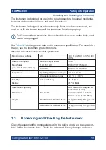
See 

Table 3-1

 for the general data on the instrument specification. For more infor-

mation, see the instrument product brochure.

Table 3-1: General data on instrument specification

Mains nominal voltage

AC

100 / 115 / 230 V (

±

10 %) 50 /

60 Hz

Power consumption

Maximum input power

230 W

Mains fuses
(fuse size: 5 mm x 20 mm)

110/115 V AC

IEC 60127 T2.5H250V

230 V AC

IEC 60127 T5.0H250V

Temperature

Operating temperature range

°

C to + 40 

°

C

Storage temperature range

- 20 

°

C to + 70 

°

C

Humidity

Non-condensing

5 % to 80 %

Display


3.5 

"

 (QVGA)

Rack mount capability


R&S HZN96 rack adapter 2U

(P/N: 3638.7813.02)

Dimensions

W x H x D

222 mm x 96 mm x 446 mm
(8.74 in x 3.78 in x 17.56 in)

Weight

R&S NGA101, R&S NGA141

6.6 kg (14.55 lb), 6.9 kg (15.21

lb)

R&S NGA102, R&S NGA142

7.0 kg (15.43 lb), 7.3 kg (16.09

lb)

3.3


Unpacking and Checking the Instrument

Check the equipment for completeness using the delivery note and package con-
tents list for the various items. Check the instrument for any damage and loose

Unpacking and Checking the Instrument

Summary of Contents for 5601.8002.02

Page 1: ...R S NGA100 Power Supply Series Getting Started 5601890202 Version 03 Æ1ç22 Sie haben Fragen oder wünschen eine Beratung Angebotsanfrage unter 07121 51 50 50 oder über info datatec de Distributed by ...

Page 2: ...0V 2A Power Supply 80 W 5601 8002 05 2021 Rohde Schwarz GmbH Co KG Mühldorfstr 15 81671 München Germany Phone 49 89 41 29 0 Email info rohde schwarz com Internet www rohde schwarz com Subject to change data without tolerance limits is not binding R S is a registered trademark of Rohde Schwarz GmbH Co KG Trade names are trademarks of the owners 5601 8902 02 Version 03 R S NGA100 Throughout this man...

Page 3: ...sic Safety Instructions and the product documentation in a safe place and pass them on to the subsequent users Riesgo de lesiones y daños en el instrumento El instrumento se debe usar de manera adecuada para prevenir descargas eléctricas incendios lesiones o daños materiales No abrir la carcasa del instrumento Lea y cumpla las Instrucciones de seguridad elementales suministradas con el instrumento...

Page 4: ...die Produktdokumentation gut auf und geben Sie diese an weitere Benutzer des Produkts weiter Risque de blessures et d endommagement de l appareil L appareil doit être utilisé conformément aux prescriptions afin d éviter les électrocutions incendies dommages corporels et matériels N ouvrez pas le boîtier de l appareil Lisez et respectez les consignes de sécurité fondamentales fournies avec l appare...

Page 5: ...이 기기는 업무용 A급 전자파 적합기기로서 판매자 또는 사용자는 이 점을 주의하시기 바라며 가정외의 지역에서 사용하는 것을 목적으로 합니다 1171 0200 78 01 ...

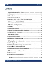
Page 6: ...tended Operation 11 3 3 Unpacking and Checking the Instrument 12 3 4 Setting Up the Instrument 14 4 Instrument Tour 15 4 1 Overview of Controls 15 4 2 Switching On the Instrument 20 5 Trying Out the Instrument 22 5 1 Selecting the Channels 22 5 2 Setting the Output Voltage and Current Limit 22 5 3 Activating the Channels Output 23 5 4 Storing Recalling of Instrument Settings 23 6 Maintenance and S...

Page 7: ...Contents R S NGA100 4 Getting Started 5601 8902 02 03 ...

Page 8: ...e control a complete description of the remote control commands with programming examples and information on maintenance and instrument interfaces Includes the contents of the getting started manual The online version of the user manual provides the complete contents for immedi ate display on the internet Basic safety instructions Contains safety instructions operating conditions and further impor...

Page 9: ...ich you can find on a label on the rear panel 1 4 Release Notes Open Source Acknowledgment The release notes list new features improvements and known issues of the cur rent firmware version and describe the firmware installation The open source acknowledgment document provides verbatim license texts of the used open source software It can also be downloaded from the instrument See www rohde schwar...

Page 10: ...is case all linked channels are turned off when the set channel reaches its limit The EasyArb function allows channel 1 Ch 1 to have freely definable voltage and current sequences with a timeframe as short as 10 ms It allows you to vary the voltage or current limit during a test sequence for example to simulate differ ent charging conditions of a battery With EasyRamp function the R S NGA100 provi...

Page 11: ...amage to the instrument In addition read and observe the safety instructions in the following sec tions Notice that the data sheet may specify additional operating condi tions Risk of instrument damage during operation An unsuitable operating site or test setup can cause damage to the instru ment and the connected devices Ensure the following operating conditions before you switch on the instrumen...

Page 12: ...Setting Up the Instrument 14 3 1 Safety Recommendations on secure operation The R S NGA100 is designed to operate at local workplaces or in secured networks LAN It should not be accessible from the internet because of a potential security risk e g attackers could misuse or damage your device Please always install the latest firmware It is highly recommended that you work closely with your IT depar...

Page 13: ...rly that the power cables are in perfect condition Choose suitable protective measures and installation types to ensure that the power cord cannot be damaged and that no harm is caused by tripping hazards or from electric shock for instance Risk of electric shock It is prohibited to disconnect the earthed protective connection inside or out side of the instrument If it is assumed that a safe opera...

Page 14: ...se by personnel familiar with the potential risks of measuring electrical quantities For safety reasons the instrument may only be connected to properly installed safety socket outlets Separating the ground is prohibited The power plug must be inserted before signal circuits may be connected Use only the power cord included in the delivery package See Delivery package on page 13 Before each measur...

Page 15: ...ains nominal voltage AC 100 115 230 V 10 50 60 Hz Power consumption Maximum input power 230 W Mains fuses fuse size 5 mm x 20 mm 110 115 V AC IEC 60127 T2 5H250V 230 V AC IEC 60127 T5 0H250V Temperature Operating temperature range 5 C to 40 C Storage temperature range 20 C to 70 C Humidity Non condensing 5 to 80 Display 3 5 QVGA Rack mount capability R S HZN96 rack adapter 2U P N 3638 7813 02 Dime...

Page 16: ...ould be used If you do not have the original packaging use sufficient padding to pre vent the instrument from moving around inside the box Pack the instru ment in antistatic wrap to protect it from electrostatic charging Secure the instrument to prevent any movement and other mechanical effects during transportation Delivery package The package contents contain the following items R S NGA100 power...

Page 17: ...tions 3 4 2 Rack Mounting The instrument can be installed in a 19 rack using the rack adapter R S HZN96 P N 3638 7813 02 Proceed according to the installation instructions supplied with the rack adapter Ambient temperature Operate R S NGA100 power supply in an area where the ambient temper ature is within 5 C to 40 C The R S NGA100 power supply is fan cooled and must be installed with sufficient s...

Page 18: ...w of Controls 4 1 1 Front Panel The front panel of the R S NGA100 is as shown in Figure 4 1 The function keys and navigation controls are located at the right side of the display The various connectors are located below the display and function keys The following power supply models are available Table 4 1 Power supply models Models Number of output channels NGA101 0 V 35 V 6 A NGA141 0 V 100 V 2 ...

Page 19: ... measurement settings and functions are displayed in the individual channel section There is a status bar above the channel section to indicate the functions used and operation mode of the instrument For a detailed description on screen layout see section Screen Layout in the User Manual Function keys 2 Function keys are means of input for manual operation of the instrument func tions When a funct...

Page 20: ...on Navigation Controls in the User Manual Output channels 4 Depending on the instrument models up to two output channels are available for output of power to the connected load See Table 4 1 USB connector 5 USB Type A connector is provided for connecting a USB flash drive to perform firmware update data logging and store screen captures The USB flash drive file system supports FAT32 only Power key...

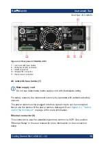
Page 21: ...h inadequate rating For safety reasons the instrument can only be operated with authorized safety sockets The power cable must be plugged in before signal circuits can be connected Never use the product if the power cable is damaged See Chapter 4 2 Switch ing On the Instrument on page 20 for more information Ethernet connector 8 This connector is used for establishing remote control via SCPI See s...
Page 22: ... Trigger I O option NGA K103 must be installed for this function to be available in the instrument Rear panel connector 11 Shock Hazard Do not turn on AC power when connecting wires to the rear panel connec tor Tightened all wires connected to the terminal block Output terminals Either the output terminals at the front panel or the rear panel connector at the back panel can be used Both terminals ...

Page 23: ...s the mains voltage between 100 V 115 V and 230 V See Table 3 1 for the fuse rating To set the correct fuse rating use a tool e g a flat screwdriver to move the selec tor according to the voltage selector label To select 100 V slide both voltage selector to the left To select 115 V slide both voltage selector facing inward To select 230 V slide both voltage selector to the right 4 2 Switching On t...

Page 24: ...use holder to its position in the panel To switch on the instrument 1 Connect the power cable to the AC power connector on the rear panel of the R S NGA100 2 Connect the power cable to the socket outlet 3 Press Power key on the front panel The instrument performs a system check boots the operating system and starts the R S NGA100 firmware By default all output channels are turned off when the inst...

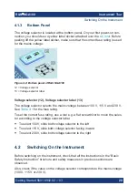
Page 25: ...ng mode The voltage at channel 1 is highlighted in blue 2 Move to the desired parameter via the arrow keys 3 Rotate the knob to adjust its value Alternatively 1 Press Voltage or Current key on the front panel 2 For the two channel R S NGA100 press the desired channel key to activate the respective voltage or current limit setting of that channel The value on the respective channel becomes editable...

Page 26: ...t key to activate the channel output Depending on the instrument operating mode the display font color changes to green in CV constant voltage mode and red in CC constant current mode 5 4 Storing Recalling of Instrument Settings The instrument settings can be stored in the instrument memory by long pressing the Store Recall key followed by the desired memory location key M1 to M5 The previous save...
Page 27: ...ep in mind that the casing is not waterproof Do not use any liquids for cleaning Cleaning agents solvents thinners acetone acids and bases can dam age the front panel labeling plastic parts and display The display may only be cleaned with an appropriate glass cleaner Rub the dis play with a dry clean and lint free cloth Do not allow cleaning fluid to enter the instrument 6 2 Contacting Customer Su...

Page 28: ...100 25 Getting Started 5601 8902 02 03 Contact information Contact our customer support center at www rohde schwarz com support or fol low this QR code Figure 6 1 QR code to the Rohde Schwarz support page Contacting Customer Support ...

Page 29: ...nel AC inlet with fuse holder 17 Digital I O connector 17 Ethernet connector 17 USB connector 17 Voltage selector 17 Release notes 6 S Safety instructions 5 Setting up the instrument Bench operation 14 Rack mounting 14 Switching off the instrument 20 Switching on the instrument 20 T Trying out the instrument Activating the channels output 22 Selecting the channels 22 Setting the output voltage and...

Reviews: