Arbitrary and Function Generator
R&S AM300
E-1007.9922.12
6-86
Operating manual, 02/2005
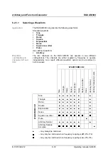
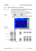
Setting the Signal Amplitude
Application
The signal amplitude can be entered in different forms:
V+
,
V-
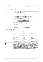
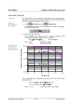
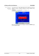
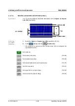
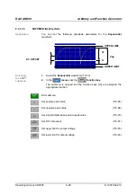
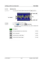
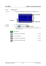
- as a positive and negative peak value relative to the
zero line on the measurement diagram
V
pp
- as a peak-to-peak value ( 6-79)
Note:
When the amplitude parameters change the other parameters
associated with them are computed and synchronized.
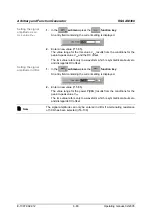
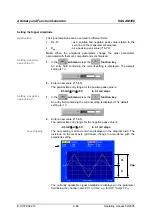
Setting a positive
peak value V+
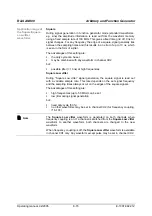
1.
In the
submenu
press the
function key
.
An entry field containing the current setting is displayed. The default
setting is 1 V.
2.
Enter a new value ( 5-55).
The permissible entry range for the positive peak value is:
0.5 mV
≤
V+
≤
+5 V
in 0.1 mV steps
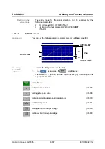
Setting a negative
peak value V-
1.
In the
submenu
press the
function key
.
An entry field containing the current setting is displayed. The default
setting is -1 V.
2.
Enter a new value ( 5-55).
The permissible entry range for the negative peak value is:
-0.5 mV
≥
V-
≥
-5 V
in 0.1 mV steps
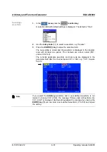
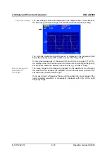
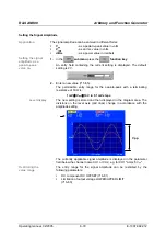
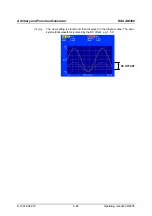
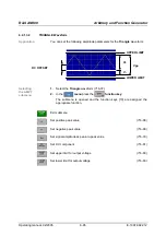
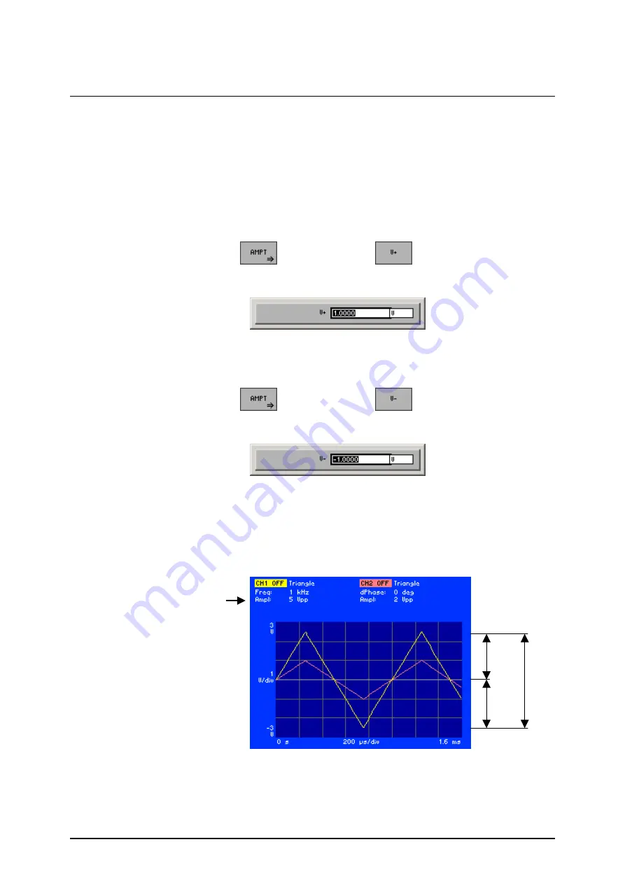
Level display
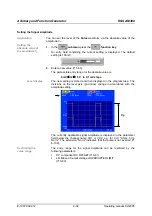
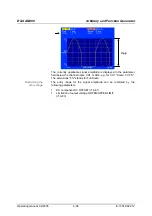
The new setting is stored and then displayed in the diagram area. The
divisions on the level axis (grid lines) change in accordance with the
amplitude setting.
The currently applicable signal amplitude is displayed in the parameter
field below the channel name CH1 or CH2, e.g. for CH1 "Ampl: 5 V
pp
“.
V+
Vpp
V-
Summary of Contents for AM 300
Page 2: ...02 2005 ...

