R&S ENV4200
Operating the V-Network
User Manual 1107.2470.12 - 03
E-25
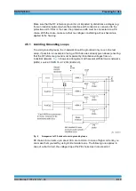
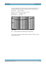
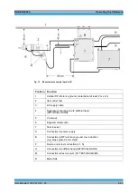
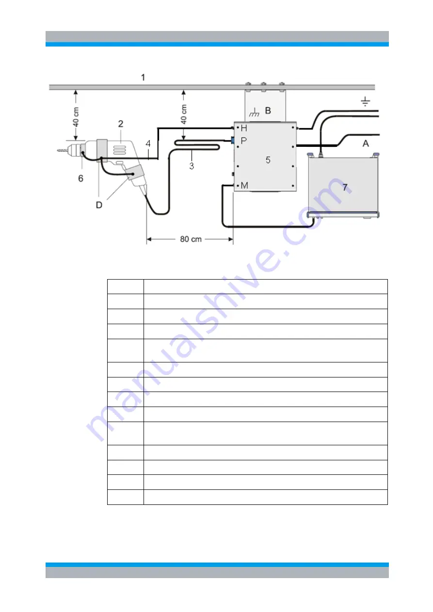
Fig. 10
Measurement example (hand drill)
Position Function
1
Vertical RF reference ground, metal panel at least 2 m x 2 m
2
Item under test
3
AC supply cable
4
Separate connecting line to artificial hand
(ARTIFICIAL HAND)
5
V-network
6
Exposed metal collar
7
Test receiver
A
Connection to power supply
B
Connection to RF reference ground, low induction
(e.g. brass plate 0.2 mm thick)
P
Device under text connection (L1, N)
H
Connection to artificial hand (ARTIFICIAL HAND)
M
Connection to test receiver (TO TEST RECEIVER)
D
Metal foils

