background image

DC power supply

DC Power Supply and Battery Operation

6

Installation Manual 1321.3937.02 ─ 02

Figure 2-2: Attaching the holding plate to the rear panel of the instrument

6. Set the power switch on the rear panel of the instrument to "I" ([ON]).

7. Hold the DC power supply (4) to the edge of the holding plate and press it

towards the rear panel.

Figure 2-3: Attaching the DC power supply to the rear panel

8. Secure the DC power supply on the holding plate using the screw (5).

Installing the DC power supply

Summary of Contents for FSV-B32

Page 1: ...DC Power Supply and Battery Operation R S FSV B30 B32 B34 Installation Manual 1321393702 Version 02 EWU2 ...

Page 2: ...hldorfstr 15 81671 München Germany Phone 49 89 41 29 0 Email info rohde schwarz com Internet www rohde schwarz com Subject to change data without tolerance limits is not binding R S is a registered trademark of Rohde Schwarz GmbH Co KG Trade names are trademarks of the owners 1321 3937 02 Version 02 DC Power Supply and Battery Operation Throughout this manual products from Rohde Schwarz are indica...

Page 3: ... battery Do not open or disassemble the bat tery Do not expose the battery to high temperatures such as open flames hot sur faces and sunlight Only use the battery with the designated Rohde Schwarz product Only use the appropriate Rohde Schwarz charger to charge the batteries If the batteries are improperly charged there is a risk of explosion For charging and discharging temperature ranges see th...

Page 4: ...ed double insulation in accordance with DIN EN IEC 61010 UL 3111 CSA C22 2 No 1010 1 or DIN EN IEC 60950 UL 1950 CSA C22 2 No 950 Provide current limitation in accordance with DIN EN 61010 1 Appendix F2 1 Use a cable no lon ger than 3 m 2 1 Installing the DC power supply The DC power supply is attached to the rear panel of the instrument To install the DC power supply on the instrument Installing ...
Page 5: ...e it by the corner protector supplied with the B30 option to ensure sufficient ventilation of the DC power supply 4 Remove the three screws 2 from the rear panel 5 Secure the holding plate 3 to the rear panel using three screws 2 Use the upper holes of the holding plate for R S FSV and R S ESRP the lower holes for R S ESR Use the screws supplied with the option Installing the DC power supply ...
Page 6: ...anel of the instrument 6 Set the power switch on the rear panel of the instrument to I ON 7 Hold the DC power supply 4 to the edge of the holding plate and press it towards the rear panel Figure 2 3 Attaching the DC power supply to the rear panel 8 Secure the DC power supply on the holding plate using the screw 5 Installing the DC power supply ...

Page 7: ...s recommended that you fuse the voltage source with maximum 25 A 1 Switch off the DC power supply to avoid long term damage to the device 2 NOTICE Risk of instrument damage Do not connect or disconnect the DC cable to the DC power supply while the DC power supply is on Connecting the cable falsely or while the voltage source is powered can result in long term damage to the cable or the device Conn...

Page 8: ... power supply to I A green LED indicates that the DC power supply is ready for operation If overvoltage or undervoltage occurs the DC power supply switches off auto matically A red LED indicates the error state 2 Press the ON OFF key on the front panel of the instrument A green LED above the ON OFF key indicates that the instrument is ready for operation To switch off the instrument 1 Press the ON...

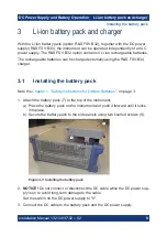
Page 9: ...FSV B34 charger 3 1 Installing the battery pack Note the Chapter 1 Safety Instructions for Lithium Batteries on page 3 1 Attach the battery pack 7 to the top of the instrument a Place the battery pack on the instrument and push it forward until it locks into place b Secure the battery pack to the side panels using two knurled screws 8 Figure 3 1 Installing the battery pack 2 NOTICE Do not connect ...

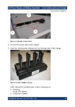
Page 10: ...batteries of the R S FSV B32 battery pack simulta neously Charge the battery before using it for the first time Following a long storage period it can be necessary to charge and discharge the battery several times to reach full capacity For charging use the R S FSV B34 charger Look up the following details in the data sheet Charging conditions Recharging interval to avoid deep discharge 1 Unscrew ...

Page 11: ... 02 Figure 3 3 Battery compartment 4 Connect the power cable to the charger 5 Insert the rechargeable batteries into the charging slots of the charger Figure 3 4 R S FSV B34 charger LEDs indicate the operating state of each charging slot Charging Green LED flashes Charging completed Charging the batteries ...

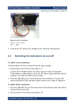
Page 12: ...witching the instrument on and off To switch on the instrument The instrument is off but connected to the DC power supply 1 Set the switch on the battery pack to I 2 Set the switch on the DC power supply to I A green LED indicates that the DC power supply is ready for operation If overvoltage or undervoltage occurs the DC power supply switches off auto matically A red LED indicates the error state...

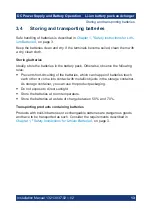
Page 13: ...wing rules Prevent short circuiting of the batteries which can happen if batteries touch each other or come into contact with metallic objects in the storage container As storage container you can use the product packaging Do not expose to direct sunlight Store the batteries at room temperature Store the batteries at a state of charge between 50 and 70 Transporting products containing batteries Pr...

Reviews: