Operating Basics
R&S
®
NGA100
30
User Manual 5601.8919.02 ─ 03
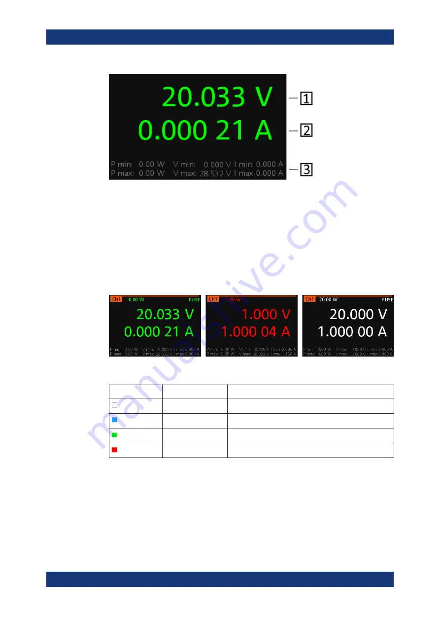
Figure 5-2: Channel display area for one-channel model
1 = Output voltage displays in volt. The display resolution for voltage is three digits after the decimal point
2 = Output current displays in ampere. The display resolution for current is five digits after the decimal point
3 = Channel history information displaying the historical maximum and minimum channel information (P min,
P max, V min, V max, I min and I max)
Operating mode
Different font colors on the screen are used to differentiate the various output status
and operating conditions of the instrument. It is easy to know and confirm the different
output status and operating conditions of the instrument by looking at the colors.
Figure 5-3: Color coding of difference operating conditions
Color
Operating mode
Description
OFF mode
Output is OFF
Editing mode
A solid blue cursor is shown when an item is selected.
Active outputs are operated in a constant voltage mode.
Active outputs are operated in a constant current mode.
5.2
Front Panel Keys
For an overview of the front panel keys, see
Front Panel Keys


