Power Supply NGMO
Operation
4-8
4.00 / 07-2004
manual setting keys are disabled except the local key and those to
change the display mode. This makes it easier for software deve-
lopers to verify that their software is running correctly.
When a lock command has been received from the IEEE interface
the NGMO2 enters the lock state. In this state all manual settings
are completely disabled. "
LOCK
" is displayed instead of "
REM
".
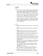
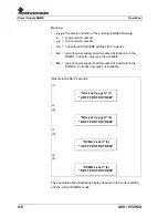
Example 2:
is similar to example 1 except that channel B has been
selected using the CHN key.
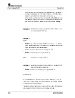
Example 3:
line 1:
•
DVMA
means that currently the DVM measurement input of chan-
nel A has been selected. The value of the voltage applied to chan-
nel A: DVM input is currently displayed.
•
z.zzz
is the value of the measured voltage in volts.
•
DVMA
: is selected by pressing the CHN key.
line: 2
is similar to example 1: line: 2.
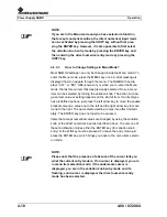
Example 4:
is similar to example 3, except that the voltage of DVM
input of channel B is displayed.
•
DVMB
: can also be selected by pressing the CHN key.
End
of startup
Now, the NGMO2 is in the main function mode. This mode allows the
setting of the output voltage, the current limit, the overvoltage protecti-
on and the overcurrent protection.
The startup settings depend on the setting of menu item 29 (See desc-
ription below for further information on recalling settings).
Summary of Contents for NGMO1
Page 8: ...Power Supply NGMO Tables 4 Version 4 00 07 2004 ...
Page 14: ...Power Supply NGMO Safety 2 2 4 00 07 2004 ...
Page 51: ...Operation Power Supply NGMO 4 00 07 2004 4 29 Fig 4 7 Status model structure ...
Page 52: ...Power Supply NGMO Operation 4 30 4 00 07 2004 ...
Page 84: ...Power Supply NGMO Ordering Information 6 2 4 00 07 2004 ...

