Operation
Power Supply NGMO
4.00 / 07-2004
4-23
4.5 Measurements
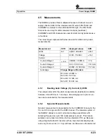
The NGMO2 provides three multiplexed measure channels on each
supply channel (A/B) for the measurement of output VOLTAGE and
CURRENT as well as for the additional DVM input. The VOLTAGE
channel is used only for static measure functions (readback),
CURRENT and DVM channels are used for static and dynamic measu-
re functions.
The value ranges represented below are valid for static and dynamic
measurements.
Measurement
-OVR
displayed values
OVR
DVM
-6 V
-5.999 - 25.999 V
≥
26 V
Voltage
-
0.000 - 15.999 V
≥
16 V
Current
Current Range 1
≥
-4 A
-3.9999 - 7.0000 A
> 7 A
Current Range 2
-
0.00 - 510.00 mA
> 510 mA
Current Range 3
-
0.0000 - 5.1000 mA
> 5.1 mA
Autorange
Change Range at Borders
R1 to R2: 0.5000 A
R2 to R3: 5.00 mA
R3 to R2: 5.1000 mA
R2 to R1: 510.00 mA
4.5.1
Reading back Voltage (V), Current (I), DVM
The sample interval for the static measurements (readback) is settable
between 2 and 200 ms in 1-ms steps. An averaging over up to ten va-
lues can be selected for this measurements.
4.5.2 Dynamic
Measurements
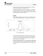
Dynamic measurements are available for the CURRENT channel in the
5 A and 0.5 A range and for the DVM channel. The measure system of
the NGMO2 allows to record current and voltage waveforms with
sampling frequencies up to 100 k-samples per second . That means
samples can be taken and stored in time intervals off 10 µs. Because
using a Sigma-Delta AD converter with an high internal sampling rate,
even very short events (<< 10 µ) will have an influence on the delivered
Summary of Contents for NGMO1
Page 8: ...Power Supply NGMO Tables 4 Version 4 00 07 2004 ...
Page 14: ...Power Supply NGMO Safety 2 2 4 00 07 2004 ...
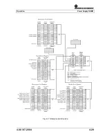
Page 51: ...Operation Power Supply NGMO 4 00 07 2004 4 29 Fig 4 7 Status model structure ...
Page 52: ...Power Supply NGMO Operation 4 30 4 00 07 2004 ...
Page 84: ...Power Supply NGMO Ordering Information 6 2 4 00 07 2004 ...

