R&S OSP
Instrument Functions
Module Functions
Quick Start Guide 1505.3896.62 - 14
107
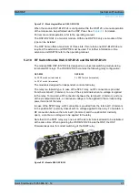
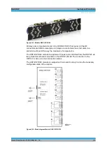
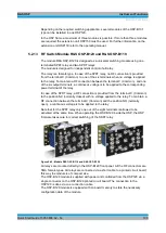
Figure 5-49: Module R&S OSP-B142 (variant .03 with 3 DP3T switches)
The relays are mounted directly in the module front panel. All the RF connectors are
SMA female types. All relays are plugged into a kind of backplane; this way the module
is of compact size and no cabling to the relays is required.
The R&S OSP-B142 module is supplied with power and controlled from the R&S OSP
base unit via a single interface connector on the module’s printed circuit board; the
connection is done via a single connection cable.
The R&S OSP-B142 module is equipped with on-board memory to store the
configuration data of the module.
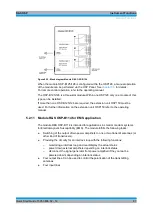
The R&S OSP-B142 exists in four different variants:
Variant
Relay configuration
OSP-B142 V03
3 x DP3T relay, sold state, w/o external termination
OSP-B142 V11
1 x SPDT relay, sold state, with external termination
OSP-B142 V12
2 x SPDT relay, sold state, with external termination
OSP-B142 V13
3 x SPDT relay, sold state, with external termination
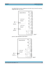
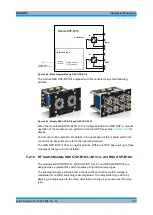
The sketch below shows the details of each DP3T relay. Each of the three DP3T relays
is built-up by three individual solid state switches.
Summary of Contents for OSP-B011
Page 132: ......


