R&S OSP
Getting Started
R&S OSP Panel Functions
Quick Start Guide 1505.3896.62 - 14
42
3.3.6 Controlling the R&S OSP-B101/-B106/-B107/-B111/-B127/-B132
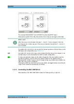
The module R&S OSP-B101 contains six RF switches of SPDT type.
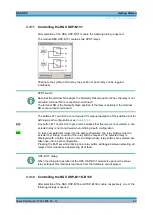
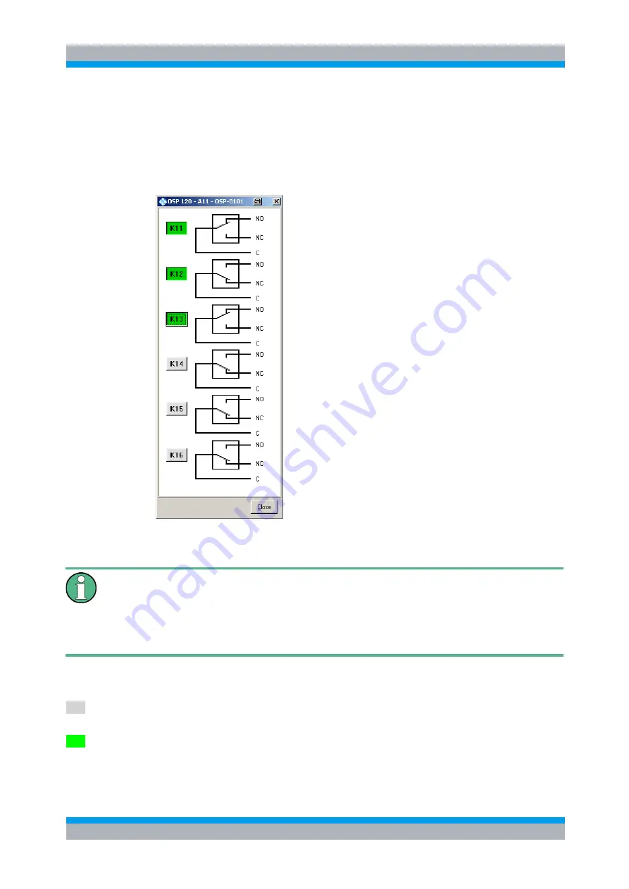
After selection of the R&S OSP-B101 module the following dialog is opened.
The module R&S OSP-B101 contains six RF switches of SPDT type, which is shown in
the OSP-B101 dialog.
Clicking to the symbol of the relay, the position of each relay can be toggled
individually.
SPDT switch
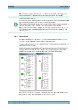
Note that the terminal NC assigns the Normally Closed position. When the relay is not
activated, terminal NC is connected to terminal C.
The terminal NO is the Normally Open position. If the relay is activated, the terminal
NO is connected to terminal C.
The buttons K11 up to K16 are not required for manual operation of the switches, but
for defining a path configuration.
K12
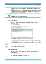
Any button K11 up to K16 in grey color indicates that this relay is not selected. A non
selected relay is not considered when defining a path configuration.
K11
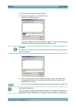
To take over particular relays into the path configuration, the relay buttons must be
selected by clicking on each of the relay buttons required. The selected relay is
displayed with a button in green color. All relays whose relay buttons are selected are
Summary of Contents for OSP-B011
Page 132: ......


