R&S OSP
Instrument Functions
R&S OSP Instrument Frame
Quick Start Guide 1505.3896.62 - 14
76
5.1.2 R&S OSP Module Slots
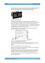
The R&S OSP offers three slots for installation of R&S OSP modules. The modules are
installed from the rear side of the instrument. A maximum of three R&S OSP modules
can be configured. If more R&S OSP modules are required, the R&S OSP can be
extended by the version R&S OSP150. The extension unit R&S OSP150 is controlled
from the R&S OSP120 or OSP130 by CAN bus Interface.
Refer to the operating manual
for detailed information on the extension unit
R&S OSP150.
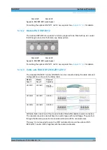
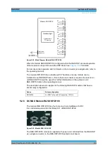
Slot A11
Slot A12
Slot A13
Figure 5-4: R&S OSP Module Slots
The slots are designated with A11, A12 and A13. The same order is used when
addressing the modules; i.e. R&S OSP module 1 corresponds to slot A11 etc.
In principle the R&S OSP modules can be installed in the slots in any order. A slot
which is not occupied will be shown as empty by the OSP Panel application.
Module Slots
The depth of the module slot A11 is limited. Only modules with a depth < 70 mm like
the modules R&S OSP-B101, R&S OSP-B102, R&S OSP-B103, R&S OSP-B107,
R&S OSP-B111 or R&S OSP-B112 can be operated in this slot!
R&S OSP-B106 can be placed in slots A11+ A12 or A12 + A13.
For installation of the modules see the corresponding installation procedures.
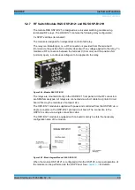
5.1.3 R&S OSP120 Version12 and Module Slots
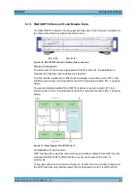
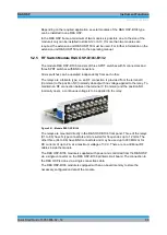
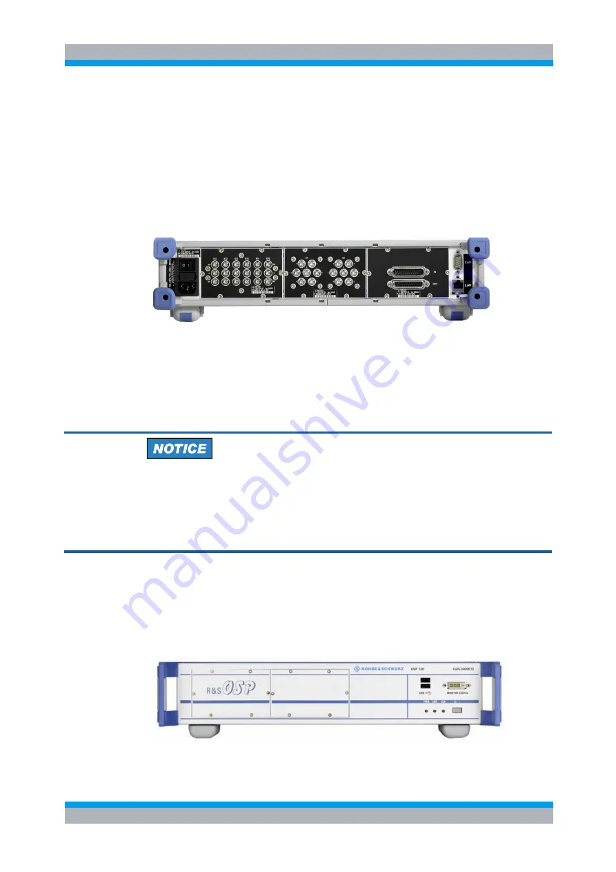
The R&S OSP120 Version 12 is designed with two slots in the front side in addition to
the three slots at the rear side as described above.
Slot A12F
Slot A13F
Summary of Contents for OSP-B011
Page 132: ......


