R&S OSP
Instrument Functions
Module Functions
Quick Start Guide 1505.3896.62 - 14
81
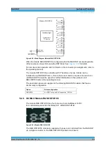
5.1.6 R&S OSP150 Version15 and Modules R&S OSP-B011/-B012
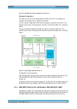
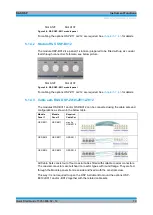
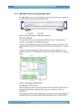
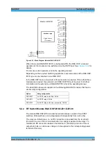
Configuring a system with instruments having the RF connectors at the front panel, the
cabling will be made easy having the RF connectors at the OSP150 front side as well.
For configuration and cabling of the modules OSP-B011 and OSP-B012 see
chapter
5.2 Module Functions
As already mentioned, the switching capability is added to the R&S OSP by installation
of an R&S OSP module. For the different kind of switching applications, a series of
R&S OSP modules is available.
The following chapters describe the function of the R&S OSP modules.
5.2.1 RF Switch Module R&S OSP-B101/-B107/-B111/-B127
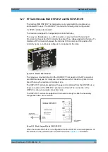
The module R&S OSP-B101 and similar as listed above consists of six SPDT
switches. All six switches can be operated independently from each other.
The relay is a failsafe type; i.e. an RF connection is provided from the terminal C
(Common) to the position NC (normally closed) with no voltage applied to the relay. To
maintain an RF connection between the terminal C (Common) and the position NO
(normally open), a continuous voltage is to be applied to the relay.
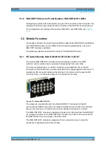
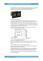
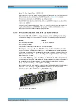
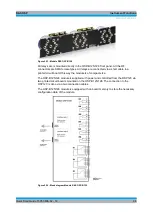
Figure 5-12: Module R&S OSP-B101
The relays are mounted directly in the R&S OSP-B101 front panel. All the RF
connectors are SMA female types. All relays are soldered into a printed circuit board;
this way the module is of compact size and no cabling to the relays is required.
The R&S OSP-B101 module is supplied with power and controlled from the R&S OSP
via a single connector on the R&S OSP-B101 printed circuit board. The connection to
the R&S OSP is done via a single connection cable.
The R&S OSP-B101 module is equipped with an on-board memory to store the
necessary configuration data of the module.
Summary of Contents for OSP-B011
Page 132: ......


