R&S OSP
Instrument Functions
Module Functions
Quick Start Guide 1505.3896.62 - 14
86
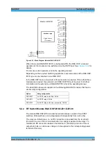
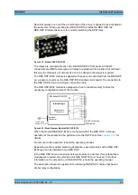
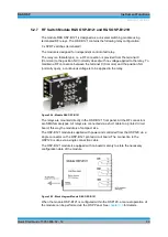
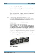
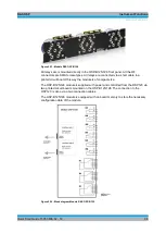
Figure 5-19: Module R&S OSP-B104
It consists of input / output ports allowing control of up to four external power transfer
relays, models Spinner BN 51 26 70 (7-16 connectors) or BN 64 00
75 (EIA 1 5/8”
flange connectors). In addition, some lines of the ports are made available at an IN /
OUT connector.
Transfer switch
The transfer relays are switched by control lines exhibiting a pulse rather than a
constant level. For that reason two lines are required to set the switch to each position.
Note that the state of the switch does not change state when the R&S OSP is turned
on (reset condition).
The Spinner transfer relays support the “carrier safety contact” concept. While turning
from one position to the other, this contact opens. If included in the interlock, the power
amplifier connected to the interlock control will be deactivated while the relay is turning.
In the final position the carrier safety contact closes again, thus closing the full interlock
chain. The power amplifier then can also be put into operate mode again.
The relays have a contact indicating the position. This line is read from the module and
used to display and verify the current status.
Delay time for Transfer switch
The transfer relays may have a settling time which cannot be neglected. Per default a
delay time of 100 msec is set up for the OSP-B104 module. The delay time allows the
relay to reach it’s final position before the new position is read back. Refer to the
operating manual for further information on how to change the delay time for the OSP-
B104 relays.
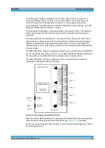
In the lower part of the module, on the outside of the lower RELAY connectors, there
are four LEDs labeled PWR 1 to PWR 4. If an LED shows a green light, the power is
OK. If the LED is off, there is a problem with the power on the corresponding
connector. In such a case, please turn off the OSP, try to correct for a possible fault in
the cabling or connected relay, turn the OSP back on and check the LED again.
In the middle between the lower RELAY connectors there are two more LEDs. The
upper of the two is labeled PWR I/O and gives a status information on the power for
the I/O connector. If the LED shows a green light, the power is OK. If the LED is off,
there is a problem with the power on the corresponding connector. In such a case,
please turn off the OSP, try to correct for a possible fault in the cabling or the
connected device, turn the OSP back on and check the LED again.
Summary of Contents for OSP-B011
Page 132: ......

